Cirkit Designer
Your all-in-one circuit design IDE
Home /
Component Documentation
How to Use Hrm: Examples, Pinouts, and Specs
Introduction
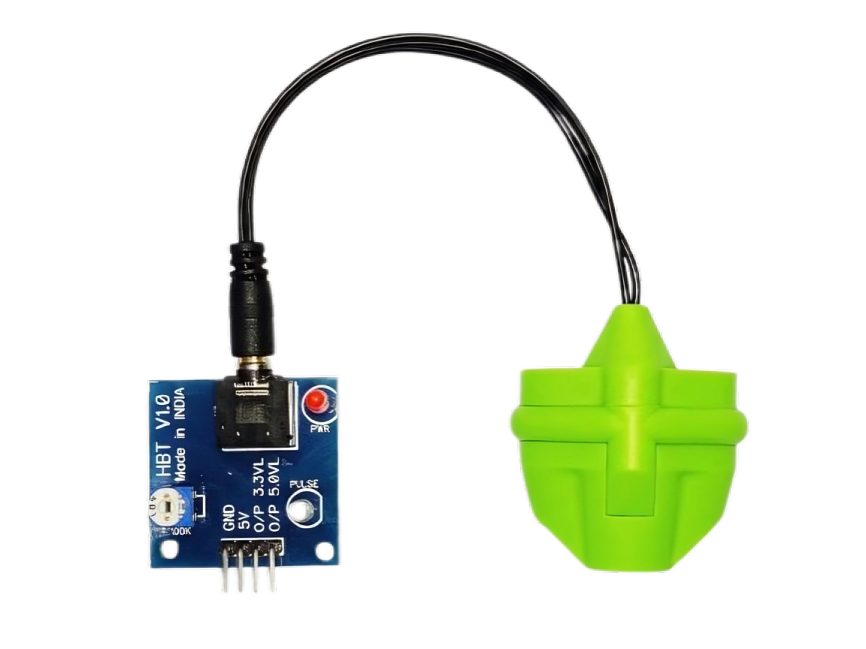
- The HRM (Heart Rate Monitor) sensor is an electronic component designed to measure the heart rate of an individual. It typically works by detecting the blood flow through a person's skin using optical or electrical methods.
- Common applications include fitness trackers, medical devices, wearable health monitors, and biofeedback systems.
Explore Projects Built with Hrm
Arduino UNO-Based Environmental Monitoring System with DHT11, NPK Soil Sensor, and GPS Module
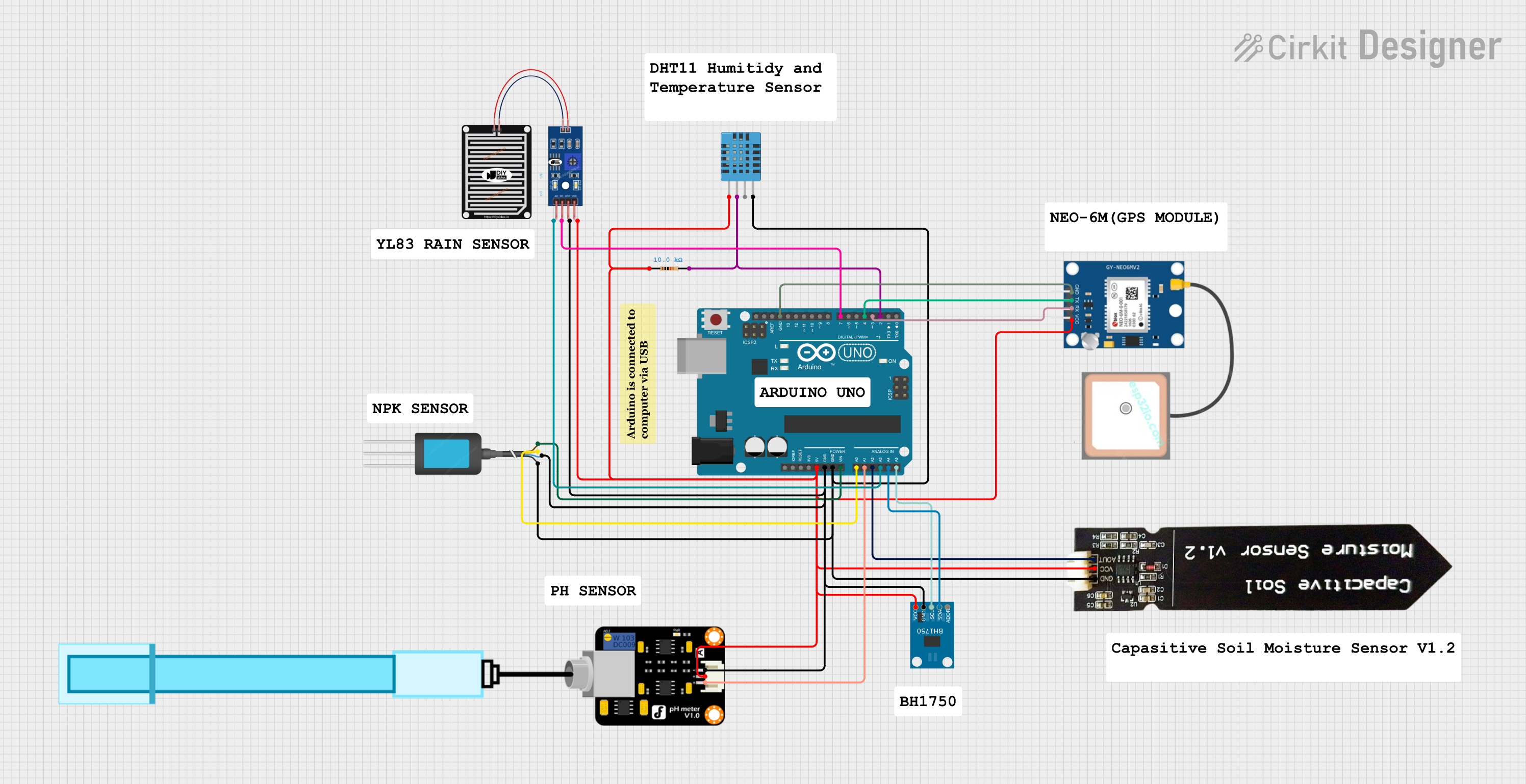
This circuit is an environmental monitoring system using an Arduino UNO to collect data from various sensors, including temperature and humidity (DHT11), soil moisture, pH, light intensity (BH1750), rain, and GPS location. The Arduino processes the sensor data and outputs it for further analysis or display.
Arduino-Controlled Smart Home System with Bluetooth, Motion Detection, and Solar Charging
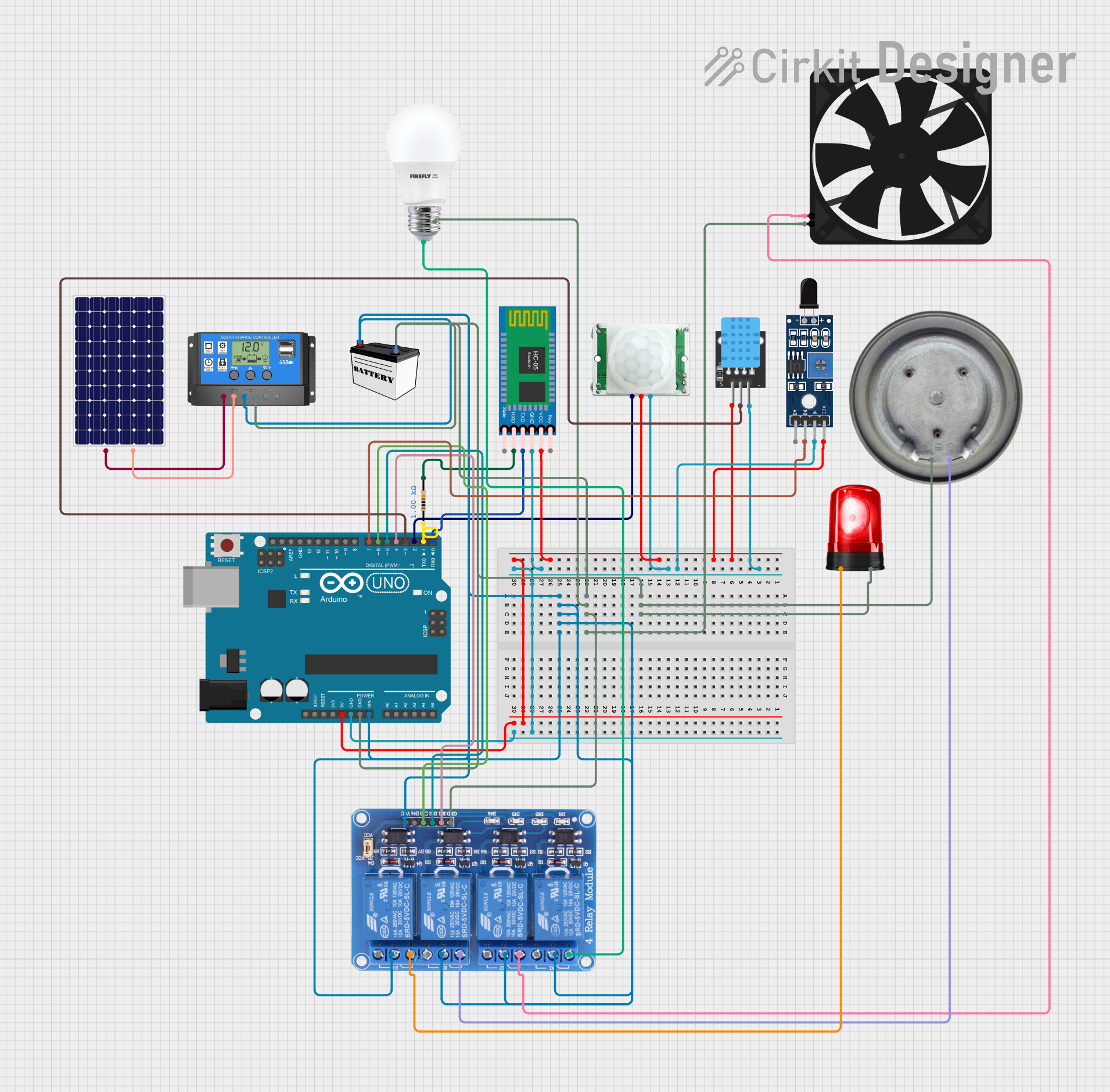
This circuit appears to be a smart control system utilizing an Arduino UNO as the central processing unit, interfacing with various sensors (PIR/Motion, DHT11 temperature and humidity, and flame sensor), a Bluetooth module for wireless communication, and a relay module to control power to a bulb, fan, heater element, and siren. The system is powered by a 12V battery charged by a solar panel through a solar charge controller. The Arduino's code structure is in place, but the specific functionality is not defined in the provided code.
Arduino UNO-Based Smart Irrigation System with Motion Detection and Bluetooth Connectivity

This circuit is a microcontroller-based control and monitoring system. It uses an Arduino UNO to read from a DHT22 temperature and humidity sensor and an HC-SR501 motion sensor, display data on an LCD, and control a water pump and an LED through a relay. The HC-05 Bluetooth module allows for wireless communication.
Arduino UNO-Based Environmental Monitoring System with DHT11, BH1750, and GPS

This circuit is an environmental monitoring system using an Arduino UNO to collect data from various sensors, including temperature and humidity (DHT11), soil moisture, pH, light intensity (BH1750), rain, and GPS location. The Arduino processes the sensor data and outputs it to a serial monitor for real-time monitoring.
Explore Projects Built with Hrm
Arduino UNO-Based Environmental Monitoring System with DHT11, NPK Soil Sensor, and GPS Module
This circuit is an environmental monitoring system using an Arduino UNO to collect data from various sensors, including temperature and humidity (DHT11), soil moisture, pH, light intensity (BH1750), rain, and GPS location. The Arduino processes the sensor data and outputs it for further analysis or display.
Arduino-Controlled Smart Home System with Bluetooth, Motion Detection, and Solar Charging
This circuit appears to be a smart control system utilizing an Arduino UNO as the central processing unit, interfacing with various sensors (PIR/Motion, DHT11 temperature and humidity, and flame sensor), a Bluetooth module for wireless communication, and a relay module to control power to a bulb, fan, heater element, and siren. The system is powered by a 12V battery charged by a solar panel through a solar charge controller. The Arduino's code structure is in place, but the specific functionality is not defined in the provided code.
Arduino UNO-Based Smart Irrigation System with Motion Detection and Bluetooth Connectivity
This circuit is a microcontroller-based control and monitoring system. It uses an Arduino UNO to read from a DHT22 temperature and humidity sensor and an HC-SR501 motion sensor, display data on an LCD, and control a water pump and an LED through a relay. The HC-05 Bluetooth module allows for wireless communication.
Arduino UNO-Based Environmental Monitoring System with DHT11, BH1750, and GPS
This circuit is an environmental monitoring system using an Arduino UNO to collect data from various sensors, including temperature and humidity (DHT11), soil moisture, pH, light intensity (BH1750), rain, and GPS location. The Arduino processes the sensor data and outputs it to a serial monitor for real-time monitoring.
Technical Specifications
- Type: Optical or electrical heart rate sensor
- Operating Voltage: 3.3V to 5V DC
- Current Consumption: ~4mA (varies by model)
- Output Signal: Analog or digital (depending on the sensor model)
- Measurement Range: 30 to 240 beats per minute (BPM)
- Accuracy: ±2 BPM (typical)
- Interface: Analog output or I2C/SPI for digital models
Pin Configuration and Descriptions
Below is a typical pin configuration for an HRM sensor with analog output:
| Pin | Name | Description |
|---|---|---|
| 1 | VCC | Power supply pin (3.3V to 5V DC) |
| 2 | GND | Ground pin |
| 3 | OUT | Analog output pin providing a voltage proportional to the heart rate signal |
For digital HRM sensors with I2C interface:
| Pin | Name | Description |
|---|---|---|
| 1 | VCC | Power supply pin (3.3V to 5V DC) |
| 2 | GND | Ground pin |
| 3 | SDA | Serial Data Line for I2C communication |
| 4 | SCL | Serial Clock Line for I2C communication |
Usage Instructions
Connecting the HRM Sensor:
- For analog sensors:
- Connect the
VCCpin to a 3.3V or 5V power source. - Connect the
GNDpin to the ground of your circuit. - Connect the
OUTpin to an analog input pin of your microcontroller (e.g., Arduino).
- Connect the
- For digital sensors:
- Connect the
VCCandGNDpins as described above. - Connect the
SDAandSCLpins to the corresponding I2C pins on your microcontroller.
- Connect the
- For analog sensors:
Important Considerations:
- Ensure the sensor is placed securely on the skin for accurate readings.
- Avoid excessive movement during measurement to reduce noise in the signal.
- Use appropriate pull-up resistors for I2C communication if required by your sensor.
Arduino UNO Example Code (for an analog HRM sensor):
// HRM Sensor Example Code for Arduino UNO
// This code reads the analog output of the HRM sensor and calculates the heart rate.

const int hrmPin = A0; // Analog pin connected to the HRM sensor's OUT pin

void setup() {
  Serial.begin(9600); // Initialize serial communication at 9600 baud
  pinMode(hrmPin, INPUT); // Set the HRM pin as input
}

void loop() {
  int sensorValue = analogRead(hrmPin); // Read the analog value from the sensor
  float voltage = sensorValue * (5.0 / 1023.0); // Convert to voltage (5V reference)

  // Print the raw sensor value and voltage to the Serial Monitor
  Serial.print("Sensor Value: ");
  Serial.print(sensorValue);
  Serial.print(" | Voltage: ");
  Serial.println(voltage);

  delay(100); // Delay for 100ms before the next reading
}
Troubleshooting and FAQs
Common Issues
No Output Signal:
- Ensure the sensor is powered correctly (check VCC and GND connections).
- Verify that the sensor is securely placed on the skin.
Inconsistent Readings:
- Minimize movement during measurement to reduce noise.
- Check for proper contact between the sensor and the skin.
I2C Communication Failure (for digital sensors):
- Verify the SDA and SCL connections.
- Ensure the correct I2C address is used in your code.
FAQs
Q: Can I use the HRM sensor with a 3.3V microcontroller?
- A: Yes, most HRM sensors are compatible with both 3.3V and 5V systems. Check the datasheet for your specific model.
Q: How do I filter noise from the sensor readings?
- A: Use a low-pass filter in your circuit or implement software-based filtering techniques.
Q: Can the HRM sensor measure heart rate through clothing?
- A: No, the sensor must be in direct contact with the skin for accurate readings.