Cirkit Designer
Your all-in-one circuit design IDE
Home /
Component Documentation
How to Use 24/12v Buck: Examples, Pinouts, and Specs
Introduction
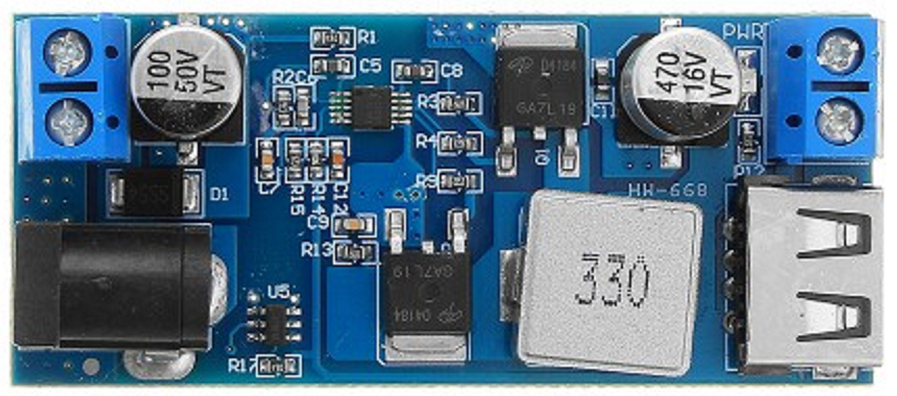
A 24/12V Buck Converter is a type of DC-DC converter that efficiently steps down an input voltage of 24 volts to a stable output voltage of 12 volts. This electronic component is widely used in automotive applications, solar power systems, and any electronic device that requires a regulated 12V DC supply from a 24V source.
Explore Projects Built with 24/12v Buck
Battery-Powered UPS with Step-Down Buck Converter and BMS

This circuit is a power management system that steps down a 240V AC input to a lower DC voltage using a buck converter, which then powers a 40W UPS. The UPS is controlled by a rocker switch and is backed up by a battery management system (BMS) connected to three 3.7V batteries in series, ensuring continuous power supply.
Battery-Powered DC Generator with XL4015 Buck Converter

This circuit consists of a 12V battery connected to a rocker switch, which controls the input to an XL4015 DC Buck Step-down converter. The converter steps down the voltage to power a DC generator, with the generator's output connected back to the converter to form a feedback loop.
USB Power Supply with Overcurrent Protection

This circuit is designed to step down voltage from a 12V battery to a lower voltage suitable for USB devices. It includes a buck converter connected to the battery through a fuse and fuse holder for overcurrent protection. The output of the buck converter is connected to a USB female port, providing a regulated power supply for USB-powered devices.
Dual Motor Control Circuit with Directional Switching and Voltage Regulation

This circuit features a 12V battery connected through a rocker switch to two buck converters, one of which steps down the voltage to power two DC mini metal gear motors, and the other is connected to a directional switch that controls a third DC mini metal gear motor. The XL4015 5A DC Buck Step-down converter's output is connected to two motors, allowing them to run at a reduced voltage, while the other buck converter's output is routed through a directional switch to control the direction of the third motor.
Explore Projects Built with 24/12v Buck
Battery-Powered UPS with Step-Down Buck Converter and BMS
This circuit is a power management system that steps down a 240V AC input to a lower DC voltage using a buck converter, which then powers a 40W UPS. The UPS is controlled by a rocker switch and is backed up by a battery management system (BMS) connected to three 3.7V batteries in series, ensuring continuous power supply.
Battery-Powered DC Generator with XL4015 Buck Converter
This circuit consists of a 12V battery connected to a rocker switch, which controls the input to an XL4015 DC Buck Step-down converter. The converter steps down the voltage to power a DC generator, with the generator's output connected back to the converter to form a feedback loop.
USB Power Supply with Overcurrent Protection
This circuit is designed to step down voltage from a 12V battery to a lower voltage suitable for USB devices. It includes a buck converter connected to the battery through a fuse and fuse holder for overcurrent protection. The output of the buck converter is connected to a USB female port, providing a regulated power supply for USB-powered devices.
Dual Motor Control Circuit with Directional Switching and Voltage Regulation
This circuit features a 12V battery connected through a rocker switch to two buck converters, one of which steps down the voltage to power two DC mini metal gear motors, and the other is connected to a directional switch that controls a third DC mini metal gear motor. The XL4015 5A DC Buck Step-down converter's output is connected to two motors, allowing them to run at a reduced voltage, while the other buck converter's output is routed through a directional switch to control the direction of the third motor.
Common Applications and Use Cases
- Powering 12V devices from a 24V battery
- Automotive electronics where the electrical system is 24V
- Solar power systems stepping down voltage for battery charging
- Robotics and hobbyist projects involving dual-voltage systems
Technical Specifications
Key Technical Details
- Input Voltage Range: 20V to 28V DC
- Output Voltage: 12V DC
- Maximum Output Current: 5A (Typical)
- Efficiency: Up to 95%
- Switching Frequency: 300kHz (Typical)
- Operating Temperature: -40°C to +85°C
Pin Configuration and Descriptions
| Pin Number | Name | Description |
|---|---|---|
| 1 | VIN | Input voltage (24V DC) |
| 2 | GND | Ground reference for both input and output |
| 3 | VOUT | Regulated output voltage (12V DC) |
| 4 | EN | Enable pin for turning the converter on/off (active high) |
| 5 | FB | Feedback pin for output voltage regulation (typically not used externally) |
Usage Instructions
How to Use the Component in a Circuit
- Connect the positive terminal of the 24V source to the VIN pin of the Buck Converter.
- Connect the ground terminal of the 24V source to the GND pin.
- The VOUT pin will provide the regulated 12V output. Connect this to the device or circuit requiring 12V.
- Optionally, connect the EN pin to a digital control signal to switch the converter on or off. A high signal (>2V) enables the converter, while a low signal (0V) disables it.
Important Considerations and Best Practices
- Ensure that the input voltage does not exceed the maximum rating to prevent damage.
- Always use a fuse on the input side to protect against overcurrent conditions.
- Place a capacitor (typically 100µF to 1000µF) close to the input and output pins to minimize voltage spikes and improve stability.
- Avoid placing high-power devices close to the converter to prevent thermal interference.
- If the EN pin is not used, connect it to VIN through a pull-up resistor to ensure the converter remains enabled.
Troubleshooting and FAQs
Common Issues Users Might Face
- Output voltage is lower than 12V: Check if the input voltage is within the specified range and that the load does not exceed the maximum output current.
- Converter is overheating: Ensure adequate ventilation and that the ambient temperature is within the operating range. Also, check for any short circuits or overloads.
Solutions and Tips for Troubleshooting
- If the output voltage is unstable, add or increase the value of the output capacitor.
- If the converter does not power on, verify the EN pin is receiving a high signal or is properly connected to VIN if not used.
- Use a multimeter to check for continuity and proper voltage levels at the input and output.
FAQs
Q: Can I adjust the output voltage?
- A: This Buck Converter is fixed at 12V output. For an adjustable output, look for a converter with an adjustable feedback (FB) pin.
Q: What is the maximum power this converter can handle?
- A: The maximum power is the product of the output voltage and maximum output current, which is 12V * 5A = 60W.
Q: Is it necessary to use the EN pin?
- A: No, the EN pin is optional for power-saving or controlled applications. If not used, ensure it is tied to VIN to keep the converter enabled.
Example Arduino UNO Connection Code
// Define the enable pin for the Buck Converter
const int enablePin = 7;

void setup() {
  // Set the enable pin as an output
  pinMode(enablePin, OUTPUT);

  // Turn on the Buck Converter
  digitalWrite(enablePin, HIGH);
}

void loop() {
  // The Buck Converter is now providing a steady 12V output
  // Add your code here to interact with devices powered by the converter
}
Note: In this example, the Arduino UNO is used to control the EN pin of the Buck Converter. The converter itself does not interface directly with the Arduino for voltage conversion purposes. Ensure that the Arduino's digital pin connected to the EN pin can handle the required logic level voltage.