How to Use Driver HG7881 for DC Engine: Examples, Pinouts, and Specs
Introduction
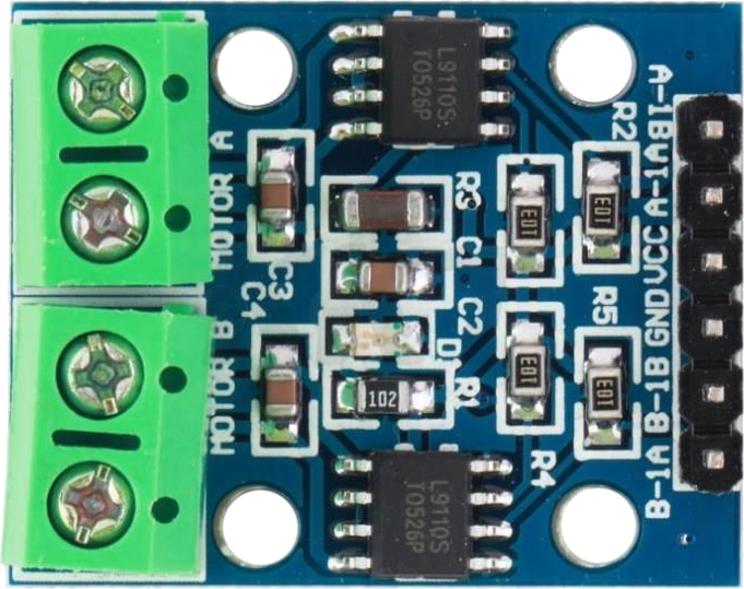
The HG7881 is a dual H-bridge motor driver IC designed for controlling DC motors and stepper motors. It enables bidirectional control of motors, allowing for forward and reverse operation. With its ability to handle high current loads, the HG7881 is widely used in robotics, automation, and small motor control applications. Its compact design and ease of use make it a popular choice for hobbyists and professionals alike.
Explore Projects Built with Driver HG7881 for DC Engine
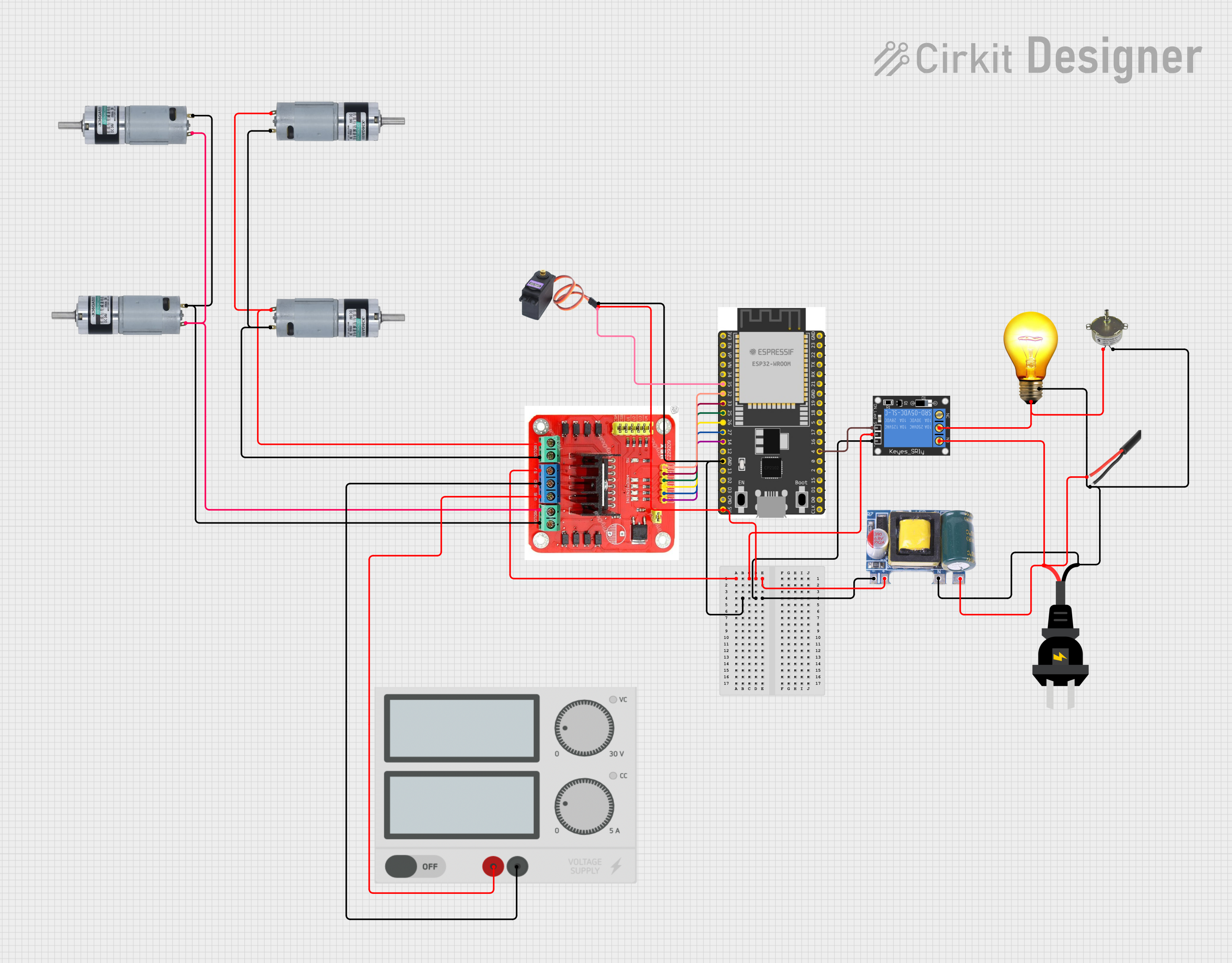


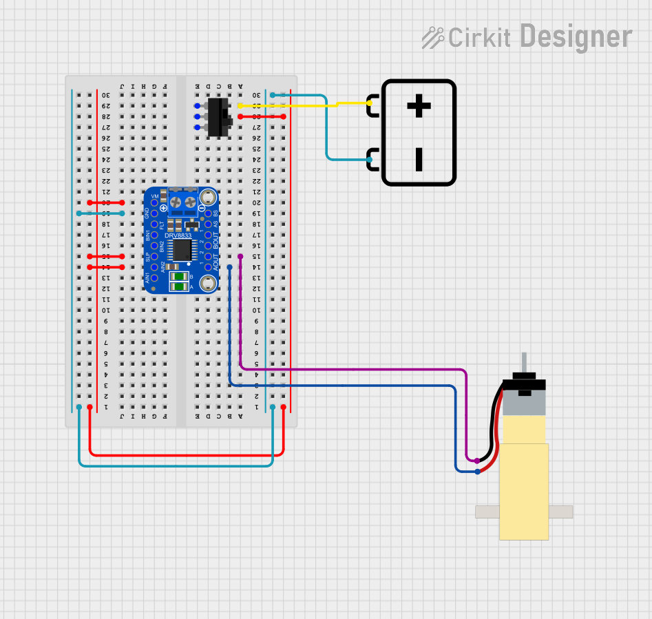
Explore Projects Built with Driver HG7881 for DC Engine
Common Applications
- Robotics and automation systems
- Remote-controlled vehicles
- Conveyor belts and small machinery
- DIY motorized projects
- Educational electronics projects
Technical Specifications
The HG7881 motor driver IC is designed to provide efficient and reliable motor control. Below are its key technical details:
| Parameter | Value |
|---|---|
| Operating Voltage | 2.0V to 7.0V |
| Maximum Output Current | 800mA per channel (continuous) |
| Logic Input Voltage | 1.8V to 7.0V |
| Output Channels | 2 (dual H-bridge) |
| Control Mode | PWM (Pulse Width Modulation) |
| Motor Type Supported | DC motors, stepper motors |
| Operating Temperature | -20°C to +85°C |
Pin Configuration and Descriptions
The HG7881 IC typically comes in an 8-pin package. Below is the pinout and description:
| Pin Number | Pin Name | Description |
|---|---|---|
| 1 | A-1A | Input signal for Motor A (controls direction) |
| 2 | A-1B | Input signal for Motor A (controls direction) |
| 3 | A-VCC | Power supply for Motor A |
| 4 | A-GND | Ground for Motor A |
| 5 | B-1A | Input signal for Motor B (controls direction) |
| 6 | B-1B | Input signal for Motor B (controls direction) |
| 7 | B-VCC | Power supply for Motor B |
| 8 | B-GND | Ground for Motor B |
Usage Instructions
The HG7881 motor driver is straightforward to use in a circuit. Below are the steps and considerations for using it effectively:
Connecting the HG7881 to a Circuit
- Power Supply: Connect the
A-VCCandB-VCCpins to the motor power supply (2.0V to 7.0V). Ensure the supply voltage matches the motor's requirements. - Ground: Connect the
A-GNDandB-GNDpins to the ground of the power supply. - Motor Connections: Connect the motor terminals to the output pins of the IC. For Motor A, use
A-1AandA-1B. For Motor B, useB-1AandB-1B. - Control Signals: Use a microcontroller (e.g., Arduino UNO) to send PWM signals to the input pins (
A-1A,A-1B,B-1A,B-1B) to control motor speed and direction.
Important Considerations
- Heat Dissipation: The IC can get warm during operation. Ensure proper ventilation or use a heatsink if necessary.
- Current Limitation: Do not exceed the maximum current rating of 800mA per channel to avoid damaging the IC.
- Decoupling Capacitors: Place a decoupling capacitor (e.g., 100µF) across the power supply pins to reduce noise and voltage fluctuations.
Example: Using HG7881 with Arduino UNO
Below is an example of how to control a DC motor using the HG7881 and Arduino UNO:
// Define motor control pins
const int motorA1 = 3; // Connect to A-1A
const int motorA2 = 5; // Connect to A-1B

void setup() {
  // Set motor control pins as outputs
  pinMode(motorA1, OUTPUT);
  pinMode(motorA2, OUTPUT);
}

void loop() {
  // Rotate motor forward
  digitalWrite(motorA1, HIGH); // Set A-1A HIGH
  digitalWrite(motorA2, LOW);  // Set A-1B LOW
  delay(2000);                // Run for 2 seconds

  // Stop motor
  digitalWrite(motorA1, LOW);
  digitalWrite(motorA2, LOW);
  delay(1000);                // Pause for 1 second

  // Rotate motor backward
  digitalWrite(motorA1, LOW);  // Set A-1A LOW
  digitalWrite(motorA2, HIGH); // Set A-1B HIGH
  delay(2000);                // Run for 2 seconds

  // Stop motor
  digitalWrite(motorA1, LOW);
  digitalWrite(motorA2, LOW);
  delay(1000);                // Pause for 1 second
}
Notes:
- Use PWM signals on the control pins to adjust motor speed.
- Ensure the Arduino's power supply is sufficient to drive the motor and the HG7881.
Troubleshooting and FAQs
Common Issues and Solutions
Motor Not Running
- Cause: Incorrect wiring or loose connections.
- Solution: Double-check all connections, especially the power supply and motor terminals.
Motor Running in One Direction Only
- Cause: One of the control pins is not receiving a signal.
- Solution: Verify the control signals from the microcontroller and ensure both input pins are properly connected.
Overheating
- Cause: Excessive current draw or insufficient ventilation.
- Solution: Ensure the motor's current draw does not exceed 800mA per channel. Add a heatsink or improve ventilation.
Noisy Operation
- Cause: Electrical noise or unstable power supply.
- Solution: Add decoupling capacitors across the power supply pins and ensure a stable power source.
FAQs
Q1: Can the HG7881 drive two motors simultaneously?
Yes, the HG7881 has two H-bridge channels, allowing it to control two DC motors independently.
Q2: Can I use the HG7881 with a 12V motor?
No, the HG7881 supports a maximum operating voltage of 7.0V. For 12V motors, consider using a different motor driver IC.
Q3: How do I control motor speed with the HG7881?
You can use PWM signals on the input pins (A-1A, A-1B, B-1A, B-1B) to adjust the motor speed.
Q4: Is the HG7881 suitable for stepper motors?
Yes, the HG7881 can control stepper motors by driving the coils in the correct sequence. However, additional programming is required for stepper motor control.
By following this documentation, you can effectively use the HG7881 motor driver in your projects.