Cirkit Designer Logo
Cirkit Designer
Your all-in-one circuit design IDE
Home / 
Component Documentation

How to Use MT3608: Examples, Pinouts, and Specs

Image of MT3608
Cirkit Designer LogoDesign with MT3608 in Cirkit Designer

Introduction

The MT3608 is a high-efficiency step-up (boost) DC-DC converter designed to increase an input voltage to a higher output voltage. It is widely used in applications where a stable, higher voltage is required from a lower voltage source, such as in battery-powered devices. The MT3608 is compact, cost-effective, and highly efficient, making it a popular choice for portable electronics, LED drivers, and small power supply circuits.

Explore Projects Built with MT3608

Use Cirkit Designer to design, explore, and prototype these projects online. Some projects support real-time simulation. Click "Open Project" to start designing instantly!
ESP32-Controlled Bluetooth Robotic Vehicle with MT3608 Boost Converters and L298N Motor Drivers
Image of Copy of Diagrama Elétrico - AutoBots (1): A project utilizing MT3608 in a practical application
This circuit is designed to control multiple DC motors and a servo motor using an ESP32 microcontroller, which is interfaced with Bluetooth for wireless control commands. The ESP32 outputs control signals to two L298N motor drivers, which in turn drive the DC motors. The MT3608 modules are used to step up the voltage from a 4 x AAA battery mount to power the motor drivers, while the servo motor is directly controlled by the ESP32.
Cirkit Designer LogoOpen Project in Cirkit Designer
Voltage Regulation System with MT3608 Boost and LM2596 Buck Converters
Image of solar system router ups: A project utilizing MT3608 in a practical application
This circuit consists of two MT3608 boost converters and an LM2596 step-down module, each connected to separate 12V power supplies. The MT3608 modules are configured to step up the voltage from their respective power supplies, while the LM2596 module steps down the voltage from a 12V battery. Diodes are used to ensure correct current flow direction, potentially for protection or isolation between different parts of the circuit.
Cirkit Designer LogoOpen Project in Cirkit Designer
ESP32-Powered Obstacle Avoidance Robot with IR and Ultrasonic Sensors
Image of projcememek: A project utilizing MT3608 in a practical application
This circuit features a 18650 Li-Ion battery connected to a TP4056 charging module, which in turn is connected to an MT3608 boost converter to step up the voltage. The output of the MT3608 powers an ESP32 microcontroller, a TCRT 5000 IR sensor, an HC-SR04 ultrasonic sensor, and an MG996R servo motor. The ESP32 is configured to control the servo motor via GPIO 27 and to receive input signals from the IR sensor and ultrasonic sensor through GPIO 14 and GPIO 13, respectively.
Cirkit Designer LogoOpen Project in Cirkit Designer
ESP32-Controlled Traffic Light and DC Motors with MT3608 Boost Converters
Image of Diagrama Elétrico - AutoBots: A project utilizing MT3608 in a practical application
This circuit is designed to control a traffic light and multiple DC motors using an ESP32 microcontroller. The ESP32's GPIO pins are connected to the traffic light to control the green, yellow, and red LEDs, and to the L298N motor drivers for controlling the speed and direction of the DC motors. The MT3608 modules are used to step up the voltage from the AAA batteries to power the motor drivers, and the MG996R servo is controlled by the ESP32 for additional actuation tasks.
Cirkit Designer LogoOpen Project in Cirkit Designer

Explore Projects Built with MT3608

Use Cirkit Designer to design, explore, and prototype these projects online. Some projects support real-time simulation. Click "Open Project" to start designing instantly!
Image of Copy of Diagrama Elétrico - AutoBots (1): A project utilizing MT3608 in a practical application
ESP32-Controlled Bluetooth Robotic Vehicle with MT3608 Boost Converters and L298N Motor Drivers
This circuit is designed to control multiple DC motors and a servo motor using an ESP32 microcontroller, which is interfaced with Bluetooth for wireless control commands. The ESP32 outputs control signals to two L298N motor drivers, which in turn drive the DC motors. The MT3608 modules are used to step up the voltage from a 4 x AAA battery mount to power the motor drivers, while the servo motor is directly controlled by the ESP32.
Cirkit Designer LogoOpen Project in Cirkit Designer
Image of solar system router ups: A project utilizing MT3608 in a practical application
Voltage Regulation System with MT3608 Boost and LM2596 Buck Converters
This circuit consists of two MT3608 boost converters and an LM2596 step-down module, each connected to separate 12V power supplies. The MT3608 modules are configured to step up the voltage from their respective power supplies, while the LM2596 module steps down the voltage from a 12V battery. Diodes are used to ensure correct current flow direction, potentially for protection or isolation between different parts of the circuit.
Cirkit Designer LogoOpen Project in Cirkit Designer
Image of projcememek: A project utilizing MT3608 in a practical application
ESP32-Powered Obstacle Avoidance Robot with IR and Ultrasonic Sensors
This circuit features a 18650 Li-Ion battery connected to a TP4056 charging module, which in turn is connected to an MT3608 boost converter to step up the voltage. The output of the MT3608 powers an ESP32 microcontroller, a TCRT 5000 IR sensor, an HC-SR04 ultrasonic sensor, and an MG996R servo motor. The ESP32 is configured to control the servo motor via GPIO 27 and to receive input signals from the IR sensor and ultrasonic sensor through GPIO 14 and GPIO 13, respectively.
Cirkit Designer LogoOpen Project in Cirkit Designer
Image of Diagrama Elétrico - AutoBots: A project utilizing MT3608 in a practical application
ESP32-Controlled Traffic Light and DC Motors with MT3608 Boost Converters
This circuit is designed to control a traffic light and multiple DC motors using an ESP32 microcontroller. The ESP32's GPIO pins are connected to the traffic light to control the green, yellow, and red LEDs, and to the L298N motor drivers for controlling the speed and direction of the DC motors. The MT3608 modules are used to step up the voltage from the AAA batteries to power the motor drivers, and the MG996R servo is controlled by the ESP32 for additional actuation tasks.
Cirkit Designer LogoOpen Project in Cirkit Designer

Common Applications

  • Powering microcontrollers and sensors from a single-cell battery
  • LED lighting systems
  • Portable power banks
  • Charging circuits for devices requiring higher voltage
  • DIY electronics projects requiring voltage conversion

Technical Specifications

The MT3608 is available as an integrated circuit (IC) or as a pre-assembled module. Below are its key technical details:

Key Specifications

Parameter Value
Input Voltage Range 2V to 24V
Output Voltage Range 2V to 28V (adjustable)
Maximum Output Current 2A (depends on input/output voltage and efficiency)
Efficiency Up to 93%
Switching Frequency 1.2 MHz
Operating Temperature -40°C to +85°C

Pin Configuration (IC Version)

Pin Number Pin Name Description
1 SW Switching node (connects to inductor)
2 GND Ground
3 FB Feedback pin (used to set output voltage)
4 EN Enable pin (active high, enables the converter)
5 VIN Input voltage supply
6 VOUT Output voltage

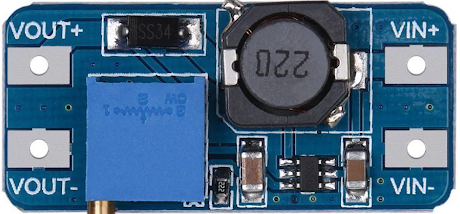
Pin Configuration (Module Version)

The MT3608 module typically has the following pins:

Pin Name Description
VIN Input voltage (2V to 24V)
GND Ground
VOUT Output voltage (adjustable via onboard potentiometer)

Usage Instructions

How to Use the MT3608 in a Circuit

  1. Connect the Input Voltage (VIN):

    • Attach the positive terminal of your power source (e.g., battery) to the VIN pin.
    • Connect the negative terminal to the GND pin.
  2. Set the Output Voltage (VOUT):

    • For the module version, adjust the onboard potentiometer to set the desired output voltage.
    • Use a multimeter to measure the output voltage while adjusting the potentiometer.
  3. Connect the Load:

    • Attach the positive terminal of your load to the VOUT pin.
    • Connect the negative terminal of your load to the GND pin.
  4. Enable the Converter (if applicable):

    • For the IC version, ensure the EN pin is pulled high to enable the converter.
    • If unused, the EN pin can be tied to VIN.

Important Considerations

  • Input Voltage Range: Ensure the input voltage is within the specified range (2V to 24V). Exceeding this range may damage the component.
  • Output Voltage Limit: Do not exceed the maximum output voltage of 28V.
  • Current Limitations: The maximum output current depends on the input voltage, output voltage, and efficiency. Avoid overloading the module.
  • Heat Dissipation: At high currents, the MT3608 may generate heat. Use proper heat management techniques, such as adding a heatsink or ensuring adequate ventilation.

Example: Using MT3608 with Arduino UNO

The MT3608 can be used to power an Arduino UNO from a lower voltage source, such as a 3.7V Li-ion battery. Below is an example circuit and code:

Circuit Connections

  • Connect the battery's positive terminal to the MT3608's VIN pin and the negative terminal to GND.
  • Adjust the MT3608's output voltage to 5V using the potentiometer.
  • Connect the MT3608's VOUT pin to the Arduino UNO's 5V pin and GND to GND.

Arduino Code Example

// Example code to blink an LED using Arduino UNO powered by MT3608
// Ensure the MT3608 output is set to 5V before connecting to the Arduino

int ledPin = 13; // Pin connected to the onboard LED

void setup() {
  pinMode(ledPin, OUTPUT); // Set the LED pin as an output
}

void loop() {
  digitalWrite(ledPin, HIGH); // Turn the LED on
  delay(1000);                // Wait for 1 second
  digitalWrite(ledPin, LOW);  // Turn the LED off
  delay(1000);                // Wait for 1 second
}

Troubleshooting and FAQs

Common Issues

  1. No Output Voltage:

    • Cause: Input voltage is too low or not connected properly.
    • Solution: Verify the input voltage is within the 2V to 24V range and check connections.
  2. Output Voltage Not Adjustable:

    • Cause: Faulty potentiometer or incorrect adjustment.
    • Solution: Ensure the potentiometer is functional and adjust it slowly while monitoring the output voltage.
  3. Overheating:

    • Cause: Excessive current draw or poor ventilation.
    • Solution: Reduce the load current or improve heat dissipation.
  4. Output Voltage Drops Under Load:

    • Cause: Input power source cannot supply enough current.
    • Solution: Use a power source with sufficient current capacity.

FAQs

Q: Can the MT3608 be used to power a Raspberry Pi?
A: Yes, but ensure the output voltage is set to 5V and the current demand of the Raspberry Pi does not exceed the MT3608's capacity.

Q: How do I calculate the output current?
A: The output current depends on the input voltage, output voltage, and efficiency. Use the formula:
[ I_{out} = I_{in} \times \frac{V_{in}}{V_{out}} \times \text{Efficiency} ]
Ensure the input current does not exceed the source's capacity.

Q: Can I use the MT3608 with a solar panel?
A: Yes, as long as the solar panel's output voltage is within the MT3608's input range and provides sufficient current.