How to Use Single Axis Joystick Potentiometer: Examples, Pinouts, and Specs
Introduction
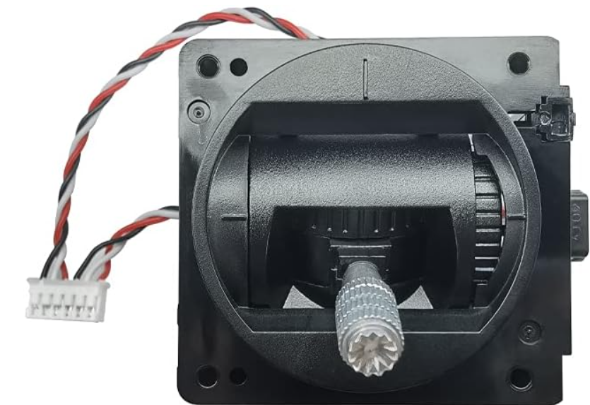
The Single Axis Joystick Potentiometer by Favor Electronics, part number 4434-FJR35-N2B10KF0-ND, is a potentiometer-based input device designed to translate physical movement or rotation along a single axis into an electrical signal. This component is commonly used for control applications in various fields, including gaming controllers, industrial controls, and assistive technology. Its intuitive operation and reliable output make it a popular choice for projects that require precise control with a simple interface.
Explore Projects Built with Single Axis Joystick Potentiometer

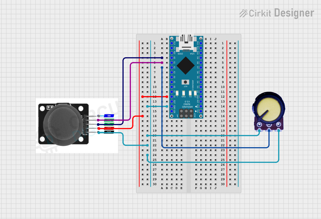
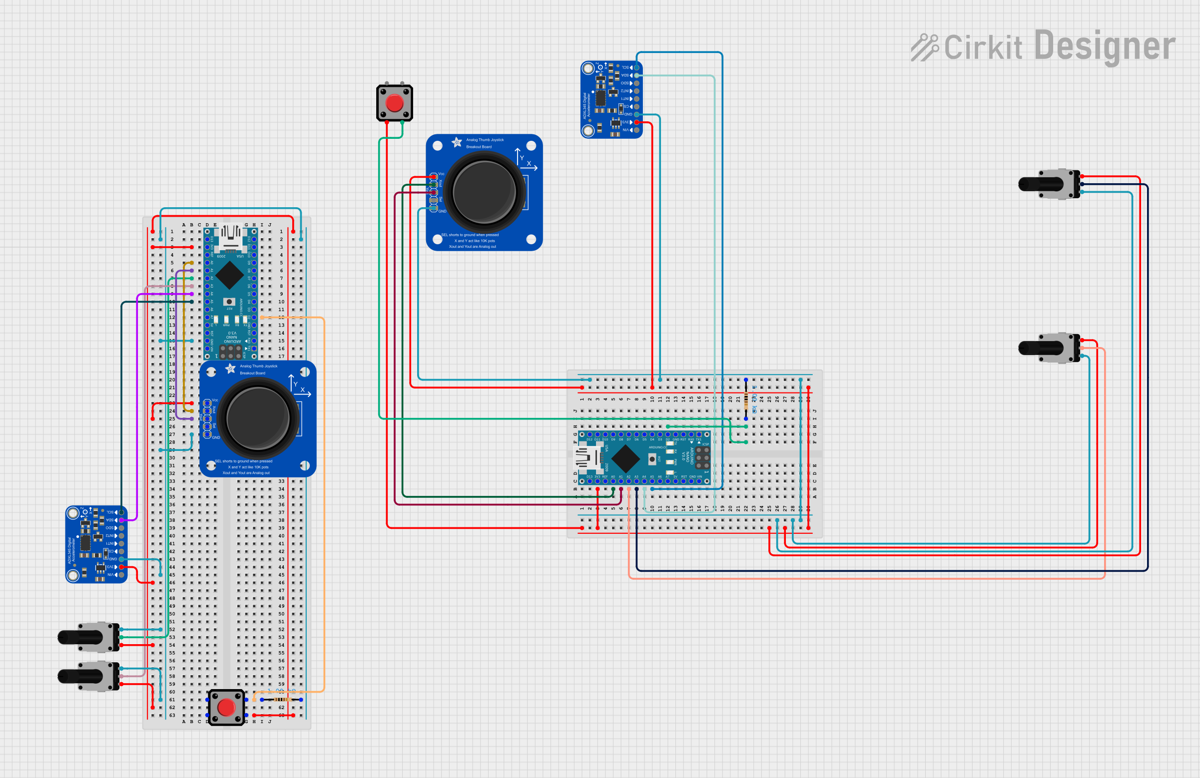
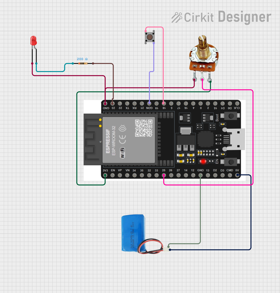
Explore Projects Built with Single Axis Joystick Potentiometer
Technical Specifications
Key Technical Details
- Resistance: 10 kΩ
- Tolerance: ±20%
- Power Rating: 0.5 W (at 40°C)
- Operating Temperature: -10°C to +70°C
- Life Cycle: 1 million cycles minimum
- Supply Voltage: Typically 5V DC for most applications
Pin Configuration and Descriptions
| Pin Number | Description | Notes |
|---|---|---|
| 1 | Ground (GND) | Connect to system ground |
| 2 | Voltage Output (VO) | Analog output signal |
| 3 | Voltage Supply (VCC) | Connect to 5V supply |
Usage Instructions
Integration into a Circuit
To use the Single Axis Joystick Potentiometer in a circuit:
- Connect pin 1 to the ground of your power supply.
- Connect pin 3 to a 5V supply.
- The voltage output on pin 2 will vary linearly with the joystick's position. Connect this to an analog input on your microcontroller, such as an Arduino UNO, to read the position.
Best Practices
- Avoid applying force that exceeds the mechanical limits of the joystick to prevent damage.
- Ensure that the power supply does not exceed the recommended voltage to avoid electrical overstress.
- Use a pull-down or pull-up resistor if necessary to ensure a stable and defined signal when the joystick is in the neutral position.
Example Code for Arduino UNO
// Define the pin connected to the joystick's output
const int joystickPin = A0;

void setup() {
  // Initialize the serial communication
  Serial.begin(9600);
}

void loop() {
  // Read the value from the joystick
  int joystickValue = analogRead(joystickPin);

  // Map and print the value to the Serial Monitor
  int position = map(joystickValue, 0, 1023, -512, 511);
  Serial.println(position);

  // Delay for a bit to avoid spamming the Serial Monitor
  delay(100);
}
Troubleshooting and FAQs
Common Issues
- Inaccurate Readings: Ensure that the joystick is properly centered and that there is no physical obstruction causing it to deviate from the neutral position.
- No Output Signal: Check all connections, especially the ground and power supply, and ensure that the joystick is not damaged.
- Erratic Behavior: This may be due to electrical noise. Adding a small capacitor between the output and ground can help filter out noise.
FAQs
Q: Can I use a different voltage supply? A: The joystick is typically designed for a 5V supply. Using a different voltage may require recalibration and could potentially damage the component.
Q: How do I calibrate the joystick? A: Calibration involves reading the neutral position value and using it as a reference in your application to determine the actual position.
Q: Is it possible to use this joystick with a digital input? A: No, the joystick provides an analog output and must be connected to an analog-to-digital converter (ADC) input to be read correctly.
Q: What is the purpose of the tolerance specification? A: Tolerance indicates the accuracy of the resistance value. A ±20% tolerance means the actual resistance can vary by this percentage from the nominal value.
For further assistance or inquiries about the Single Axis Joystick Potentiometer, please contact Favor Electronics customer support.