
Cirkit Designer
Your all-in-one circuit design IDE
Home /
Component Documentation
How to Use 电压转换器: Examples, Pinouts, and Specs
 Design with 电压转换器 in Cirkit Designer
Introduction
- 电压转换器是一种电路组件,用于将输入电压转换为不同的输出电压,以满足电路或设备的需求。它可以是升压(Boost)或降压(Buck)类型,具体取决于应用需求。
- 常见应用包括:
- 电源管理:为电子设备提供稳定的电压。
- 便携式设备:如手机、笔记本电脑等需要不同电压的设备。
- 工业控制:为传感器、控制器等提供适配电压。
- 可再生能源:如太阳能系统中的电压调节。
Explore Projects Built with 电压转换器
220V to 5V Power Supply with Transformer and Bridge Rectifier
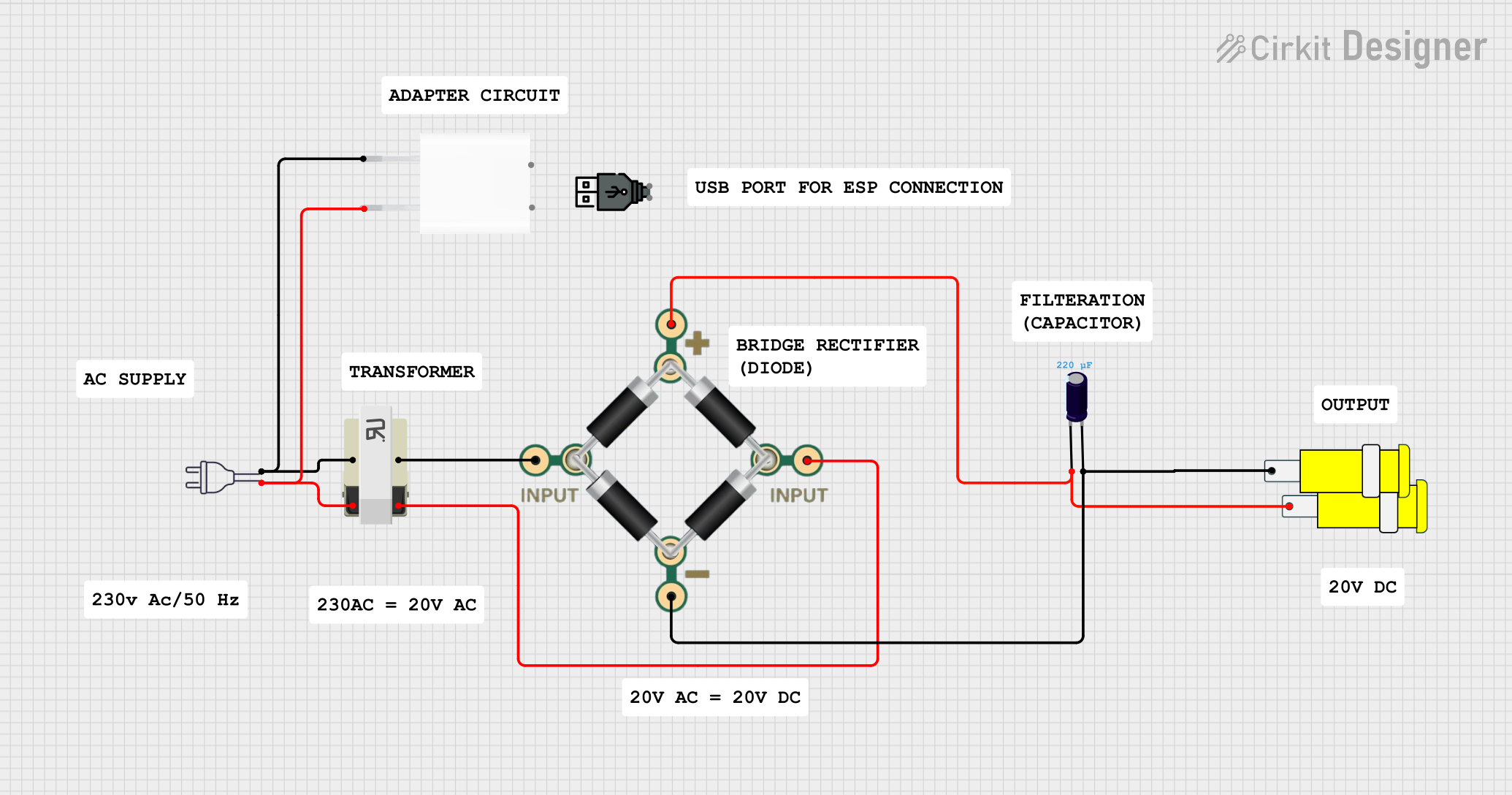
This circuit converts 220V AC power to a 5V DC output. It uses a transformer to step down the voltage, a bridge rectifier to convert AC to DC, and a capacitor to smooth the output. The final 5V DC is available through a connector.
Open Project in Cirkit DesignerAC to DC Power Supply with Transformer and Bridge Rectifier

This circuit is a basic AC to DC power supply that steps down 220V AC to a lower voltage using a transformer, rectifies it to DC using a bridge rectifier made of diodes, and smooths the output with an electrolytic capacitor. A rocker switch is used to turn the power supply on and off.
Open Project in Cirkit DesignerLM317 Voltage Regulator Circuit for Adjustable Power Supply with Transformer and Diodes
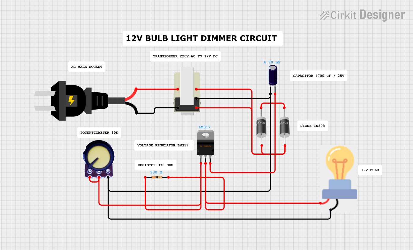
This circuit is a regulated power supply that converts AC voltage to a stable DC voltage. It uses a transformer to step down the AC voltage, diodes for rectification, an electrolytic capacitor for smoothing, and an LM317 voltage regulator to provide a stable output voltage, which is adjustable via a potentiometer. The output powers a bulb.
Open Project in Cirkit DesignerBattery-Powered DC-DC Converter System for Multi-Voltage Power Distribution
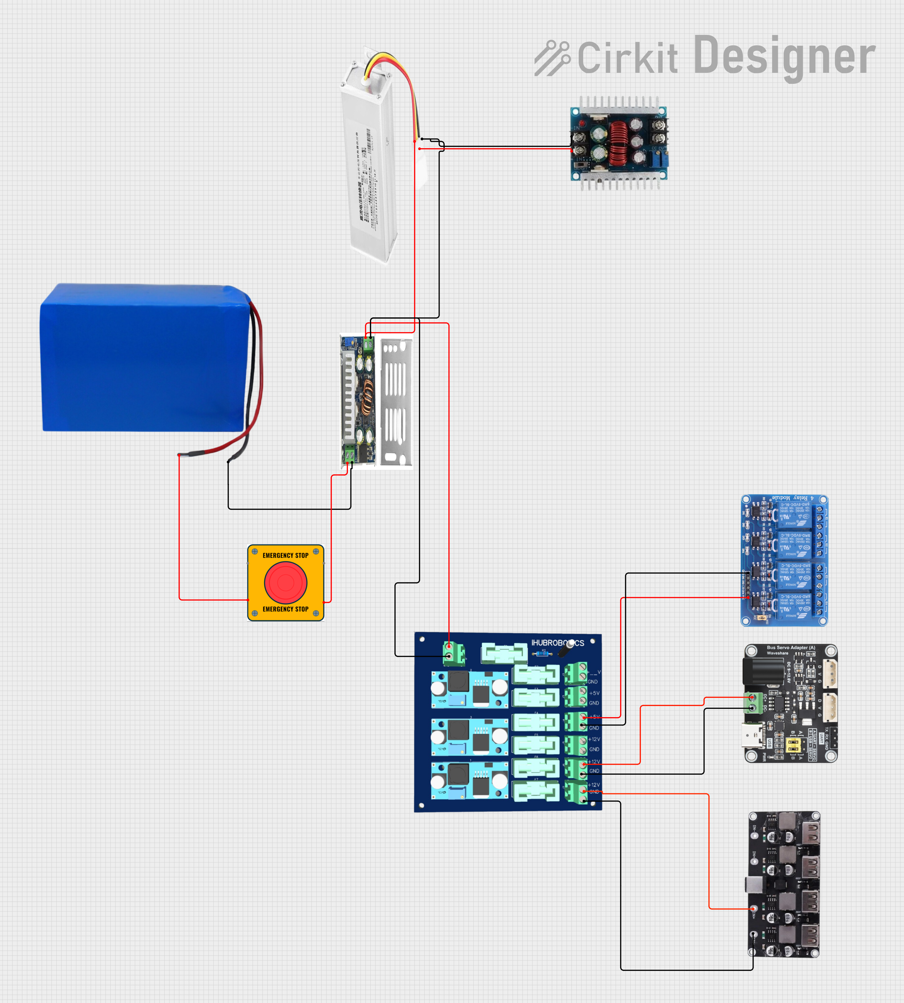
This circuit converts a 38.5V battery output to multiple lower voltage levels using a series of DC-DC converters and a power module. It includes an emergency stop switch for safety and distributes power to various components such as a relay module, USB ports, and a bus servo adaptor.
Open Project in Cirkit DesignerExplore Projects Built with 电压转换器
220V to 5V Power Supply with Transformer and Bridge Rectifier
This circuit converts 220V AC power to a 5V DC output. It uses a transformer to step down the voltage, a bridge rectifier to convert AC to DC, and a capacitor to smooth the output. The final 5V DC is available through a connector.
Open Project in Cirkit DesignerAC to DC Power Supply with Transformer and Bridge Rectifier
This circuit is a basic AC to DC power supply that steps down 220V AC to a lower voltage using a transformer, rectifies it to DC using a bridge rectifier made of diodes, and smooths the output with an electrolytic capacitor. A rocker switch is used to turn the power supply on and off.
Open Project in Cirkit DesignerLM317 Voltage Regulator Circuit for Adjustable Power Supply with Transformer and Diodes
This circuit is a regulated power supply that converts AC voltage to a stable DC voltage. It uses a transformer to step down the AC voltage, diodes for rectification, an electrolytic capacitor for smoothing, and an LM317 voltage regulator to provide a stable output voltage, which is adjustable via a potentiometer. The output powers a bulb.
Open Project in Cirkit DesignerBattery-Powered DC-DC Converter System for Multi-Voltage Power Distribution
This circuit converts a 38.5V battery output to multiple lower voltage levels using a series of DC-DC converters and a power module. It includes an emergency stop switch for safety and distributes power to various components such as a relay module, USB ports, and a bus servo adaptor.
Open Project in Cirkit DesignerTechnical Specifications
以下是电压转换器的一般技术规格(具体参数可能因型号而异):
| 参数 | 说明 |
|---|---|
| 输入电压范围 | 通常为 3V 至 40V(具体范围取决于型号) |
| 输出电压范围 | 1.2V 至 36V(可调或固定,取决于设计) |
| 输出电流 | 通常为 0.5A 至 5A(高功率型号可达 10A 或更高) |
| 转换效率 | 高达 90%-95%(取决于负载和输入/输出电压差) |
| 开关频率 | 100kHz 至 1MHz(影响效率和输出纹波) |
| 工作温度范围 | -40°C 至 +85°C(工业级) |
| 封装类型 | DIP、SMD 或模块化封装 |
Pin Configuration and Descriptions
以下是典型电压转换器模块(如 LM2596 降压模块)的引脚配置:
| 引脚编号 | 名称 | 描述 |
|---|---|---|
| 1 | VIN | 输入电压端口,连接电源正极。 |
| 2 | GND | 接地端口,连接电源负极和负载地。 |
| 3 | VOUT | 输出电压端口,连接负载正极。 |
| 4 | ADJ/FB | 调节引脚,用于设置输出电压(某些模块可能固定输出电压,无此引脚)。 |
Usage Instructions
如何在电路中使用电压转换器
- 选择合适的电压转换器:
- 根据输入电压范围、输出电压需求和负载电流选择适合的型号。
- 连接输入电源:
- 将输入电压连接到 VIN 引脚,确保输入电压在模块支持的范围内。
- 连接负载:
- 将负载连接到 VOUT 和 GND 引脚。
- 调节输出电压(可调模块):
- 使用电位器或外部电阻网络调节 ADJ/FB 引脚,设置所需的输出电压。
- 添加滤波电容:
- 在输入和输出端添加适当的滤波电容(如 10µF 至 100µF),以减少电压纹波。
使用电压转换器与 Arduino UNO
以下是一个使用 LM2596 降压模块为 Arduino UNO 提供稳定 5V 电压的示例:
电路连接
- 将电池(如 9V 电池)连接到 LM2596 的 VIN 和 GND。
- 将 LM2596 的 VOUT 和 GND 分别连接到 Arduino UNO 的 5V 和 GND 引脚。
示例代码
以下代码展示了如何使用 Arduino UNO 读取传感器数据,同时由电压转换器供电:
// 示例代码:读取模拟传感器数据
const int sensorPin = A0; // 模拟传感器连接到 A0 引脚
int sensorValue = 0;      // 用于存储传感器读取值

void setup() {
  Serial.begin(9600); // 初始化串口通信,波特率为 9600
  pinMode(sensorPin, INPUT); // 设置传感器引脚为输入模式
}

void loop() {
  sensorValue = analogRead(sensorPin); // 读取传感器的模拟值
  Serial.print("Sensor Value: ");      // 打印传感器值到串口监视器
  Serial.println(sensorValue);
  delay(1000); // 延迟 1 秒
}
重要注意事项
- 输入电压范围:确保输入电压在模块支持的范围内,过高或过低可能损坏模块。
- 散热管理:高功率应用中,模块可能会发热,建议添加散热片或风扇。
- 负载匹配:确保负载电流不超过模块的最大输出电流。
Troubleshooting and FAQs
常见问题及解决方法
输出电压不稳定
- 检查输入电压是否稳定。
- 确保输入和输出端有足够的滤波电容。
- 检查负载是否超过模块的额定功率。
模块过热
- 确保模块的散热良好。
- 检查负载电流是否超过模块的额定输出电流。
- 降低开关频率(如果模块支持调整)。
无输出电压
- 检查输入电源是否正确连接。
- 确保模块未损坏(可尝试更换模块测试)。
- 检查调节引脚(ADJ/FB)是否正确配置。
FAQs
问:电压转换器是否支持双向电压转换?
- 答:大多数电压转换器是单向的(如升压或降压)。如果需要双向转换,请选择专用的双向转换模块。
问:如何减少输出电压纹波?
- 答:在输出端添加更大的滤波电容,或使用低 ESR 电容。
问:是否可以并联多个电压转换器以增加输出电流?
- 答:不建议直接并联模块,可能导致电流不均分。建议选择更高功率的单个模块。