How to Use ME60N03 4-Channel Mosfet: Examples, Pinouts, and Specs
Introduction
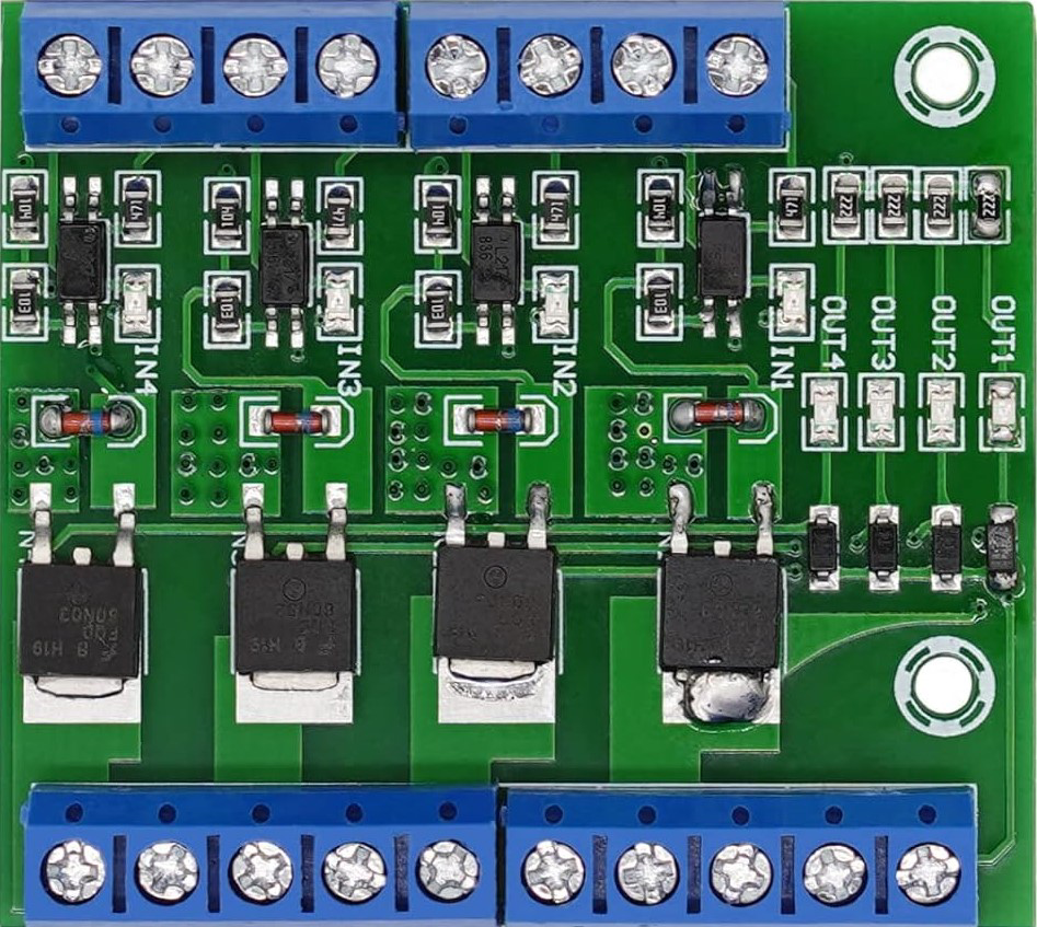
The ME60N03 4-Channel MOSFET is a semiconductor device from the ME60N03 series, designed for high-efficiency switching applications. This component is widely used in power management circuits, motor control systems, and as a switch in various electronic devices due to its ability to handle significant power levels and its fast switching speed.
Explore Projects Built with ME60N03 4-Channel Mosfet

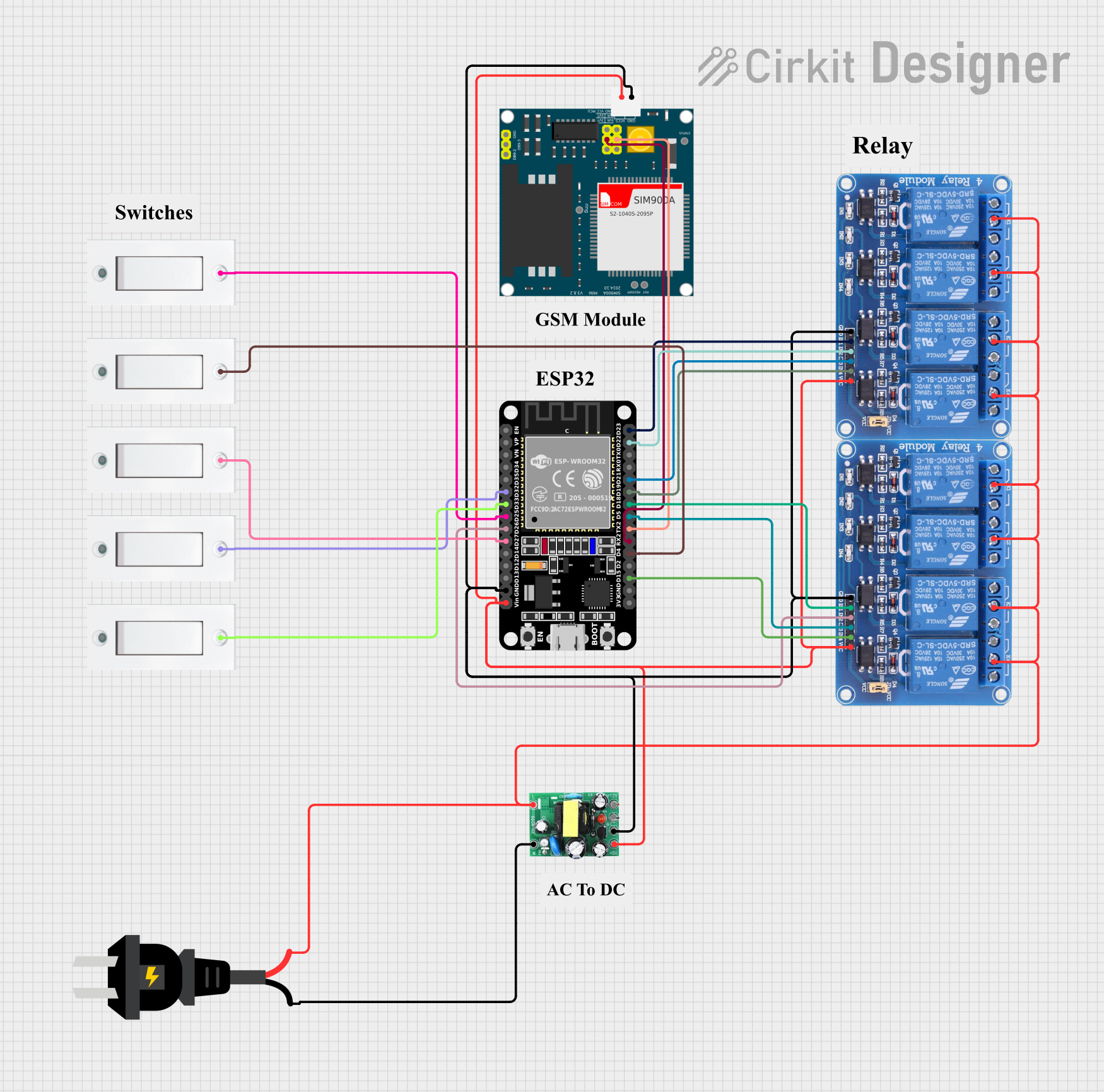


Explore Projects Built with ME60N03 4-Channel Mosfet
Common Applications and Use Cases
- Power supply circuits
- DC-DC converters
- Motor drivers and controllers
- LED lighting systems
- Battery management systems
- High-speed switching applications
Technical Specifications
Key Technical Details
- Drain-Source Voltage (Vds): 30V
- Continuous Drain Current (Id): 60A
- Pulsed Drain Current (Idm): 240A
- Power Dissipation (Pd): 50W
- Gate-Source Voltage (Vgs): ±20V
- Threshold Voltage (Vth): 1.0V to 2.5V
- Drain-Source On-Resistance (Rds(on)): 8mΩ (typical)
- Total Gate Charge (Qg): 15nC (typical)
Pin Configuration and Descriptions
| Pin Number | Name | Description |
|---|---|---|
| 1 | G1 | Gate of MOSFET channel 1 |
| 2 | S1 | Source of MOSFET channel 1 |
| 3 | D1 | Drain of MOSFET channel 1 |
| 4 | G2 | Gate of MOSFET channel 2 |
| 5 | S2 | Source of MOSFET channel 2 |
| 6 | D2 | Drain of MOSFET channel 2 |
| 7 | G3 | Gate of MOSFET channel 3 |
| 8 | S3 | Source of MOSFET channel 3 |
| 9 | D3 | Drain of MOSFET channel 3 |
| 10 | G4 | Gate of MOSFET channel 4 |
| 11 | S4 | Source of MOSFET channel 4 |
| 12 | D4 | Drain of MOSFET channel 4 |
Usage Instructions
How to Use the Component in a Circuit
Gate Drive: Apply a voltage between the gate (Gx) and source (Sx) pins to turn the corresponding MOSFET channel on. Ensure that this voltage does not exceed the maximum Vgs rating.
Load Connection: Connect the load between the drain (Dx) and source (Sx) pins. The source is typically connected to the ground or negative terminal of the power supply.
Heat Management: Due to power dissipation, ensure adequate heat sinking for the MOSFET if operating at high currents or in a high-power application.
Important Considerations and Best Practices
- Always use a gate resistor to limit inrush current and dampen oscillations.
- Implement a flyback diode when switching inductive loads to prevent voltage spikes.
- Ensure that the gate-source voltage is within the specified threshold to fully turn on the MOSFET.
- Avoid operating the MOSFET near its maximum ratings for extended reliability.
Troubleshooting and FAQs
Common Issues Users Might Face
- MOSFET Not Turning On: Ensure that the gate-source voltage is above the threshold voltage and within safe operating limits.
- Overheating: Check for adequate heat sinking and verify that the current and power dissipation are within specifications.
- Unexpected Switching: Noise on the gate pin can cause unintended switching. Use proper layout techniques to minimize noise.
Solutions and Tips for Troubleshooting
- If the MOSFET does not turn on, verify the gate voltage and the connection of the load.
- For overheating issues, improve heat dissipation with a larger heatsink or forced air cooling.
- Use a snubber circuit to reduce voltage spikes and noise if necessary.
FAQs
Q: Can I drive this MOSFET directly from a microcontroller? A: Yes, but ensure that the microcontroller can supply sufficient gate voltage to fully turn on the MOSFET.
Q: What is the purpose of the threshold voltage? A: The threshold voltage is the minimum gate-source voltage required to start conducting a small drain current.
Q: How do I choose a gate resistor value? A: The gate resistor value depends on the desired switching speed and the drive capability of the gate driver. A typical value ranges from 10Ω to 100Ω.
Q: Can I parallel multiple channels for higher current handling? A: Yes, channels can be paralleled, but ensure that the MOSFETs are well matched and that the current is evenly distributed.
Example Code for Arduino UNO
// Example code to control a single channel of the ME60N03 4-Channel MOSFET with an Arduino UNO

const int mosfetGatePin = 3; // Connect to the gate of the desired MOSFET channel

void setup() {
  pinMode(mosfetGatePin, OUTPUT);
}

void loop() {
  digitalWrite(mosfetGatePin, HIGH); // Turn on the MOSFET
  delay(1000);                       // Wait for 1 second
  digitalWrite(mosfetGatePin, LOW);  // Turn off the MOSFET
  delay(1000);                       // Wait for 1 second
}
Note: The example code provided is for controlling a single channel of the ME60N03 4-Channel MOSFET. If you need to control multiple channels, you can define additional pins and repeat the control sequence for each channel. Ensure that the Arduino can provide the necessary gate voltage for the MOSFET to turn on fully. If the required gate voltage is higher than the Arduino's output, use a gate driver circuit.