How to Use Power Limiter: Examples, Pinouts, and Specs
Introduction
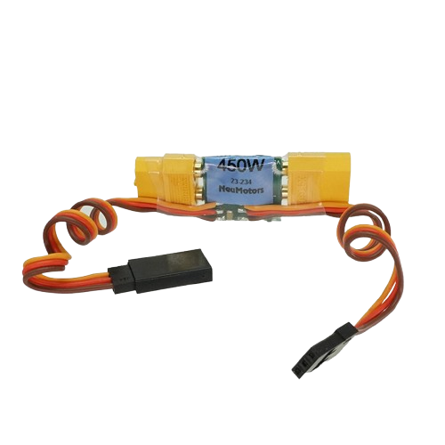
The Power Limiter (Manufacturer: Neu Motors, Part ID: 450w) is a device designed to restrict the amount of power delivered to a circuit or load. By limiting power, it prevents damage caused by excessive current or voltage, ensuring the safety and longevity of connected components. This component is particularly useful in applications where sensitive electronics or motors require protection from power surges or overloading.
Explore Projects Built with Power Limiter

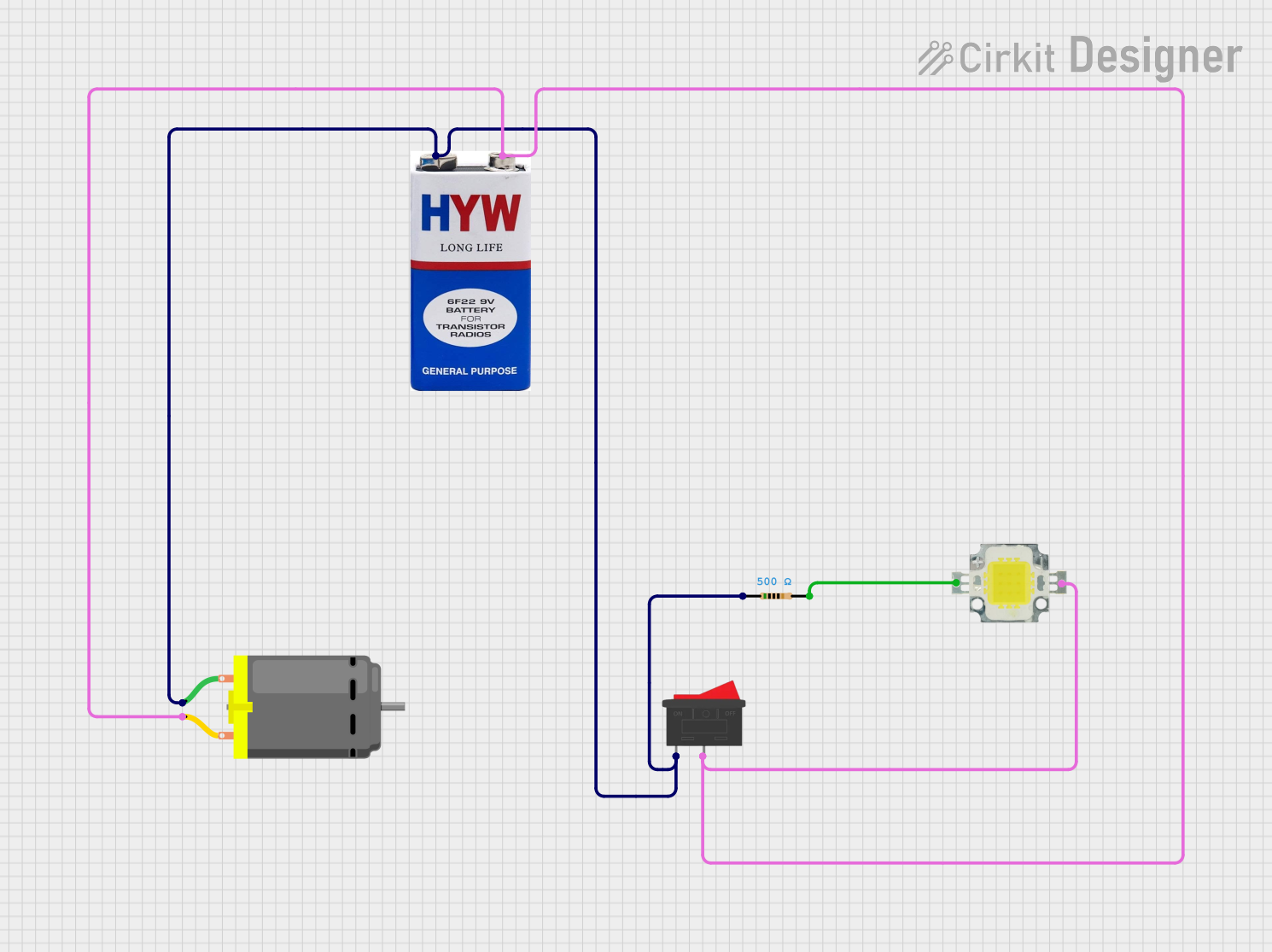


Explore Projects Built with Power Limiter
Common Applications and Use Cases
- Motor Protection: Prevents motors from drawing excessive current during startup or under heavy loads.
- Battery Management: Protects batteries from over-discharge or overcurrent conditions.
- Industrial Equipment: Ensures safe operation of machinery by limiting power to safe levels.
- Renewable Energy Systems: Regulates power delivery in solar or wind energy systems to prevent overloading.
- Consumer Electronics: Protects sensitive devices from power surges.
Technical Specifications
The following table outlines the key technical details of the Neu Motors Power Limiter (450w):
| Parameter | Value |
|---|---|
| Manufacturer | Neu Motors |
| Part ID | 450w |
| Maximum Power Rating | 450 Watts |
| Input Voltage Range | 12V - 48V DC |
| Output Voltage Range | Adjustable (10V - 45V DC) |
| Maximum Current | 10A |
| Efficiency | ≥ 95% |
| Operating Temperature | -20°C to 85°C |
| Dimensions | 75mm x 50mm x 25mm |
| Weight | 120g |
Pin Configuration and Descriptions
The Power Limiter has the following pin configuration:
| Pin Name | Type | Description |
|---|---|---|
| VIN+ | Power Input | Positive input voltage terminal (12V - 48V DC). |
| VIN- | Power Input | Negative input voltage terminal (ground). |
| VOUT+ | Power Output | Positive output voltage terminal (adjustable). |
| VOUT- | Power Output | Negative output voltage terminal (ground). |
| ADJ | Adjustment Pin | Used to set the output voltage or power limit. |
Usage Instructions
How to Use the Power Limiter in a Circuit
- Connect the Input Voltage:
- Attach the positive terminal of the power source to the
VIN+pin. - Connect the negative terminal of the power source to the
VIN-pin.
- Attach the positive terminal of the power source to the
- Connect the Load:
- Attach the positive terminal of the load to the
VOUT+pin. - Connect the negative terminal of the load to the
VOUT-pin.
- Attach the positive terminal of the load to the
- Adjust the Output:
- Use the
ADJpin to set the desired output voltage or power limit. This can typically be done using a potentiometer or external control circuit.
- Use the
- Power On:
- Turn on the power source and verify the output voltage using a multimeter.
- Ensure the load operates within the desired power limits.
Important Considerations and Best Practices
- Heat Dissipation: The Power Limiter may generate heat during operation. Ensure adequate ventilation or use a heatsink if necessary.
- Input Voltage Range: Do not exceed the specified input voltage range (12V - 48V DC) to avoid damage.
- Current Limiting: Ensure the load does not draw more than the maximum current rating (10A).
- Polarity: Double-check the polarity of connections to avoid short circuits or damage.
- Testing: Before connecting sensitive equipment, test the output voltage and power limit settings with a dummy load.
Example: Using the Power Limiter with an Arduino UNO
The Power Limiter can be used to regulate power for an Arduino UNO and its peripherals. Below is an example of how to connect and use it:
- Connect the Power Limiter's
VIN+andVIN-to a 12V DC power supply. - Set the output voltage to 5V using the
ADJpin. - Connect the
VOUT+andVOUT-to the Arduino UNO'sVINandGNDpins, respectively.
Here is a simple Arduino code snippet to monitor the voltage:
// Arduino code to monitor voltage using an analog pin
const int voltagePin = A0; // Analog pin connected to the output of the Power Limiter
float voltage = 0.0;

void setup() {
  Serial.begin(9600); // Initialize serial communication
}

void loop() {
  int sensorValue = analogRead(voltagePin); // Read the analog value
  voltage = sensorValue * (5.0 / 1023.0);   // Convert to voltage (assuming 5V reference)

  // Print the voltage to the Serial Monitor
  Serial.print("Voltage: ");
  Serial.print(voltage);
  Serial.println(" V");

  delay(1000); // Wait for 1 second before the next reading
}
Note: Ensure the Arduino's input voltage does not exceed its recommended range (7V - 12V on the
VINpin).
Troubleshooting and FAQs
Common Issues and Solutions
No Output Voltage:
- Cause: Incorrect wiring or polarity.
- Solution: Verify all connections and ensure the input voltage is within the specified range.
Overheating:
- Cause: Excessive current draw or poor ventilation.
- Solution: Reduce the load or improve heat dissipation using a heatsink or fan.
Fluctuating Output Voltage:
- Cause: Unstable input voltage or incorrect adjustment.
- Solution: Check the input voltage stability and re-adjust the
ADJpin.
Load Not Powering On:
- Cause: Output voltage too low.
- Solution: Increase the output voltage using the
ADJpin.
FAQs
Q: Can the Power Limiter handle AC input?
A: No, the Power Limiter is designed for DC input only. Using AC input will damage the device.Q: How do I know if the power limit is reached?
A: Many models include an LED indicator or signal output to indicate when the power limit is active.Q: Can I use the Power Limiter with a solar panel?
A: Yes, as long as the solar panel's output voltage and current are within the specified range.Q: Is the output voltage adjustable while the device is operating?
A: Yes, but it is recommended to make adjustments gradually and monitor the output.
By following this documentation, users can safely and effectively integrate the Neu Motors Power Limiter (450w) into their projects.