Cirkit Designer Logo
Cirkit Designer
Your all-in-one circuit design IDE
Home / 
Component Documentation

How to Use Adafruit Ultimate GPS USB: Examples, Pinouts, and Specs

Image of Adafruit Ultimate GPS USB
Cirkit Designer LogoDesign with Adafruit Ultimate GPS USB in Cirkit Designer

Introduction

The Adafruit Ultimate GPS USB is a high-performance GPS module that offers precise location and timing data. Utilizing the MediaTek MT3339 chipset, it supports various satellite systems, including GPS, GLONASS, QZSS, and more, ensuring global coverage. This module is ideal for a wide range of applications such as asset tracking, navigation, time synchronization, and DIY projects. Its USB interface simplifies connectivity to computers and microcontrollers, making it a versatile choice for both hobbyists and professionals.

Explore Projects Built with Adafruit Ultimate GPS USB

Use Cirkit Designer to design, explore, and prototype these projects online. Some projects support real-time simulation. Click "Open Project" to start designing instantly!
Arduino UNO Based GPS and GSM Tracking System
Image of priyanka rakshe: A project utilizing Adafruit Ultimate GPS USB in a practical application
This circuit features an Arduino UNO microcontroller connected to an Adafruit Ultimate GPS v3 module for receiving GPS data. The GPS module is powered by the Arduino's 5V output and communicates via serial connection using the TX and RX pins connected to the Arduino's digital pins D4 and D3, respectively. The microcontroller's code structure is set up with empty setup() and loop() functions, ready for implementing the logic to interact with the GPS module.
Cirkit Designer LogoOpen Project in Cirkit Designer
Arduino UNO Based Multi-Functional Tracking Device with GPS, GSM, and Wi-Fi Capabilities
Image of Accident Detection: A project utilizing Adafruit Ultimate GPS USB in a practical application
This circuit features an Arduino UNO as the central microcontroller, interfaced with a GPS NEO 6M module for location tracking, an esp8266 nodemcu for WiFi connectivity, and a SIM900A Mini module for GSM communication capabilities. Additionally, it includes an Adafruit ADXL335 accelerometer for motion sensing, and an LCD display for user interface, whose contrast is controlled by a potentiometer. The Arduino is programmed to coordinate these components, likely for a device that requires location tracking, wireless communication, and motion detection with a user-friendly display.
Cirkit Designer LogoOpen Project in Cirkit Designer
Arduino UNO-Based GPS and GSM Tracking System with Ultrasonic Sensing and OLED Display
Image of Radar missile  system  : A project utilizing Adafruit Ultimate GPS USB in a practical application
This circuit features an Arduino UNO as the central microcontroller, interfaced with a variety of components for sensing, communication, and display. It includes an HC-SR04 Ultrasonic Sensor for distance measurement, an Adafruit Ultimate GPS module for location tracking, a SIM800L module for GSM communication, and a 0.96" OLED display for visual output. Additionally, the circuit integrates an ESP32 for potential WiFi/Bluetooth capabilities, a servo motor for actuation, and a buzzer for audio signaling, all powered through the Arduino's voltage pins.
Cirkit Designer LogoOpen Project in Cirkit Designer
Arduino Mega 2560 Based Environmental Sensing Station with GPS, UV, and LoRa Connectivity
Image of Cansat : A project utilizing Adafruit Ultimate GPS USB in a practical application
This circuit features an Arduino Mega 2560 microcontroller as the central processing unit, interfacing with a variety of sensors and modules. It includes an MPU-6050 for motion tracking, a BMP280 for atmospheric pressure measurement, a GUVA-S12SD UV light sensor, a GPS NEO 6M module for location tracking, and a LoRa Ra-02 SX1278 module for long-range communication. The circuit is powered by a solar charger power bank connected via a USB connection, and it is designed to collect environmental data and communicate it wirelessly, likely for remote monitoring applications.
Cirkit Designer LogoOpen Project in Cirkit Designer

Explore Projects Built with Adafruit Ultimate GPS USB

Use Cirkit Designer to design, explore, and prototype these projects online. Some projects support real-time simulation. Click "Open Project" to start designing instantly!
Image of priyanka rakshe: A project utilizing Adafruit Ultimate GPS USB in a practical application
Arduino UNO Based GPS and GSM Tracking System
This circuit features an Arduino UNO microcontroller connected to an Adafruit Ultimate GPS v3 module for receiving GPS data. The GPS module is powered by the Arduino's 5V output and communicates via serial connection using the TX and RX pins connected to the Arduino's digital pins D4 and D3, respectively. The microcontroller's code structure is set up with empty setup() and loop() functions, ready for implementing the logic to interact with the GPS module.
Cirkit Designer LogoOpen Project in Cirkit Designer
Image of Accident Detection: A project utilizing Adafruit Ultimate GPS USB in a practical application
Arduino UNO Based Multi-Functional Tracking Device with GPS, GSM, and Wi-Fi Capabilities
This circuit features an Arduino UNO as the central microcontroller, interfaced with a GPS NEO 6M module for location tracking, an esp8266 nodemcu for WiFi connectivity, and a SIM900A Mini module for GSM communication capabilities. Additionally, it includes an Adafruit ADXL335 accelerometer for motion sensing, and an LCD display for user interface, whose contrast is controlled by a potentiometer. The Arduino is programmed to coordinate these components, likely for a device that requires location tracking, wireless communication, and motion detection with a user-friendly display.
Cirkit Designer LogoOpen Project in Cirkit Designer
Image of Radar missile  system  : A project utilizing Adafruit Ultimate GPS USB in a practical application
Arduino UNO-Based GPS and GSM Tracking System with Ultrasonic Sensing and OLED Display
This circuit features an Arduino UNO as the central microcontroller, interfaced with a variety of components for sensing, communication, and display. It includes an HC-SR04 Ultrasonic Sensor for distance measurement, an Adafruit Ultimate GPS module for location tracking, a SIM800L module for GSM communication, and a 0.96" OLED display for visual output. Additionally, the circuit integrates an ESP32 for potential WiFi/Bluetooth capabilities, a servo motor for actuation, and a buzzer for audio signaling, all powered through the Arduino's voltage pins.
Cirkit Designer LogoOpen Project in Cirkit Designer
Image of Cansat : A project utilizing Adafruit Ultimate GPS USB in a practical application
Arduino Mega 2560 Based Environmental Sensing Station with GPS, UV, and LoRa Connectivity
This circuit features an Arduino Mega 2560 microcontroller as the central processing unit, interfacing with a variety of sensors and modules. It includes an MPU-6050 for motion tracking, a BMP280 for atmospheric pressure measurement, a GUVA-S12SD UV light sensor, a GPS NEO 6M module for location tracking, and a LoRa Ra-02 SX1278 module for long-range communication. The circuit is powered by a solar charger power bank connected via a USB connection, and it is designed to collect environmental data and communicate it wirelessly, likely for remote monitoring applications.
Cirkit Designer LogoOpen Project in Cirkit Designer

Technical Specifications

Key Features

  • Chipset: MediaTek MT3339
  • Update Rate: Up to 10 Hz
  • Channels: 66 searching, 22 simultaneous tracking
  • Sensitivity: -165 dBm
  • Accuracy: 3 meters (without DGPS), 2.5 meters (with DGPS)
  • Hot Start: 1 second
  • Warm Start: 34 seconds
  • Cold Start: 35 seconds
  • Altitude Limit: 18,000 meters (60,000 feet) max
  • Velocity Limit: 515 meters/second (1000 knots) max
  • Acceleration Limit: Less than 4g
  • Interface: USB
  • Operating Voltage: 5V DC
  • Operating Temperature: -40°C to 85°C

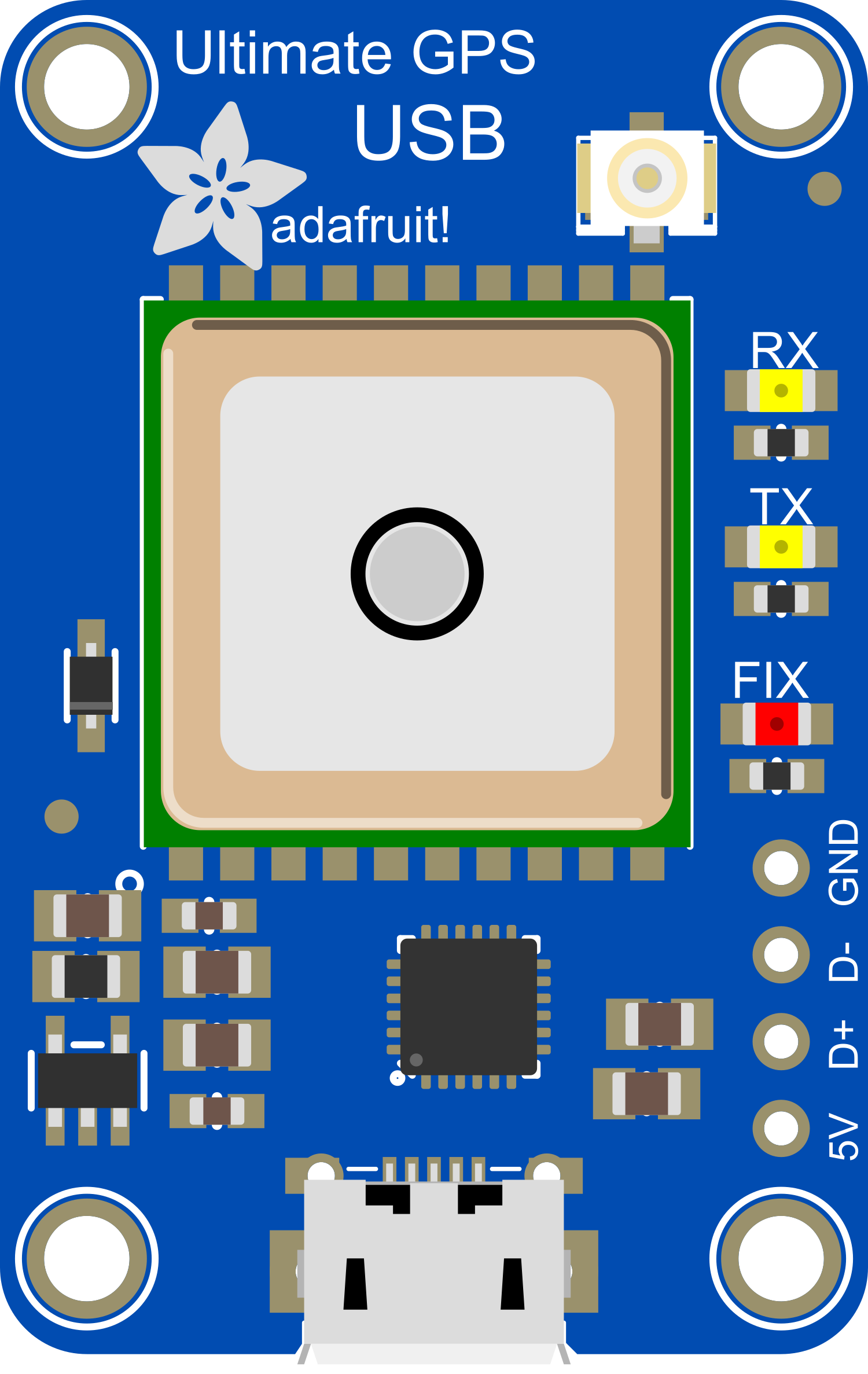
Pin Configuration and Descriptions

Pin Number Name Description
1 VCC Power supply (5V input)
2 GND Ground connection
3 TX Transmit data out (GPS to USB/Computer)
4 RX Receive data in (USB/Computer to GPS)

Usage Instructions

Connecting to a Computer

  1. Power Supply: Connect the VCC pin to a 5V USB power source and the GND pin to the ground.
  2. Data Transfer: Connect the TX and RX pins to a USB-to-serial converter if not using the direct USB connection.
  3. Drivers: Ensure that the appropriate drivers are installed on your computer for the USB-to-serial converter if required.
  4. Software: Use software like Adafruit's GPS library or other serial port tools to communicate with the GPS module.

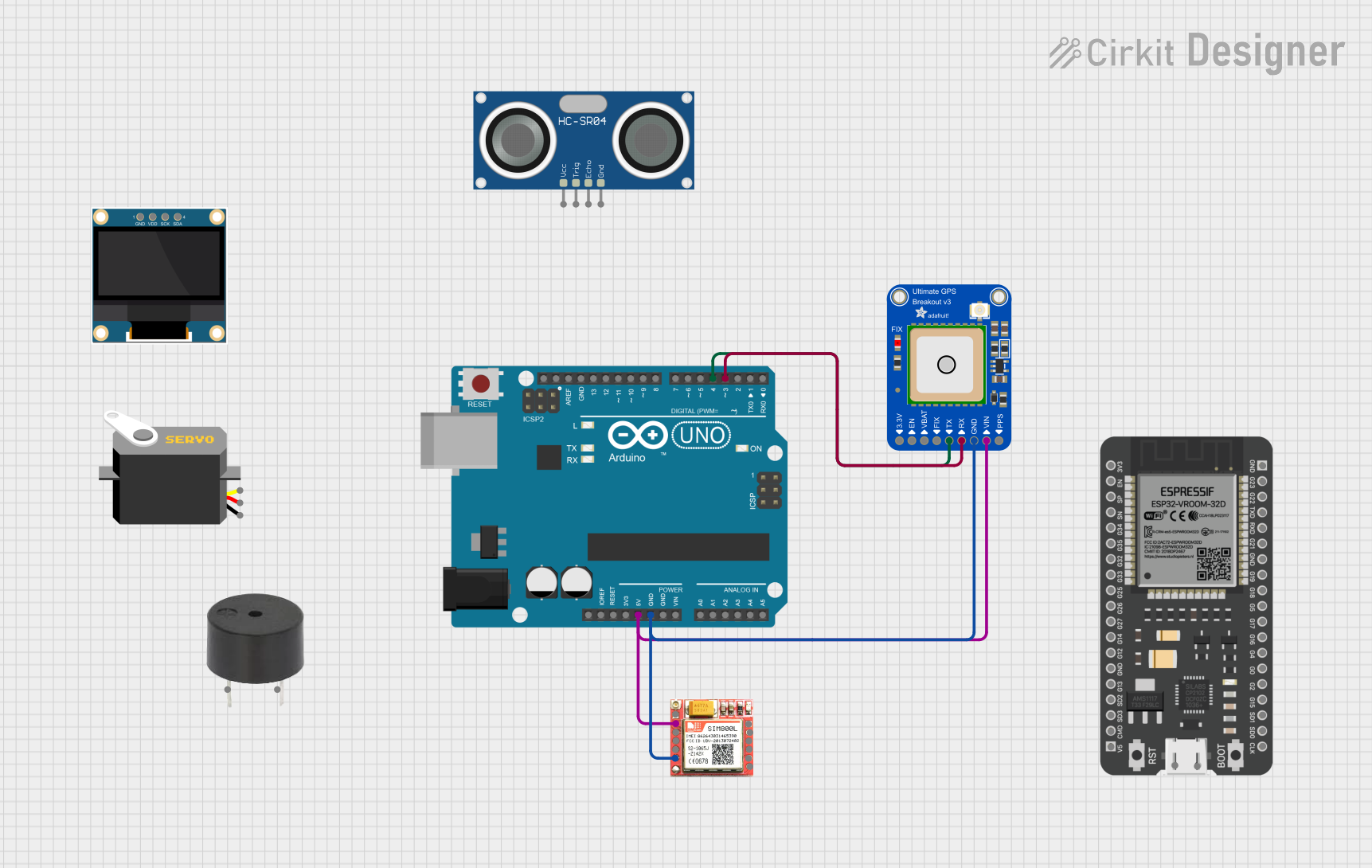
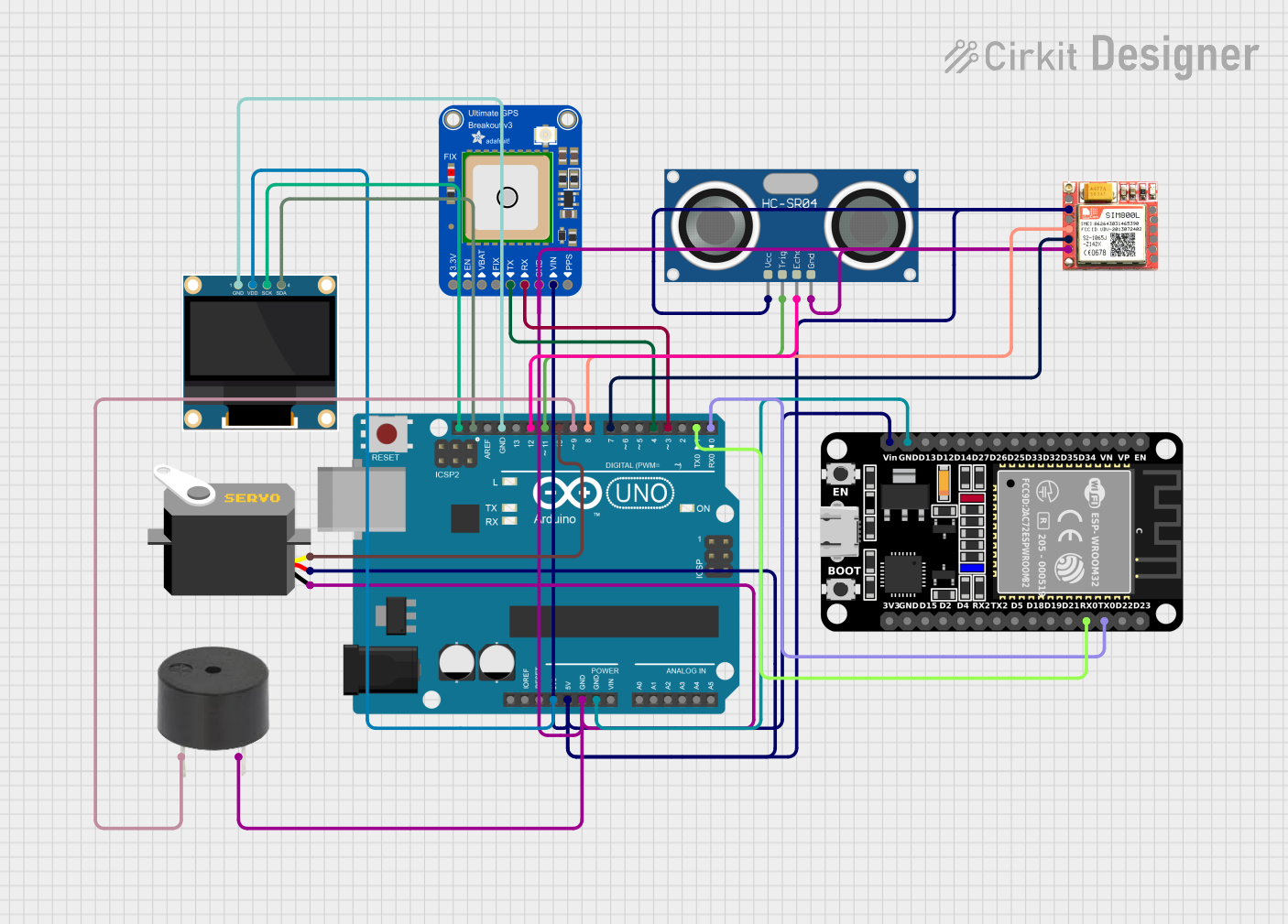
Connecting to an Arduino UNO

  1. Power Supply: Connect the VCC pin to the 5V output on the Arduino and the GND pin to one of the ground pins on the Arduino.
  2. Data Transfer: Connect the TX pin of the GPS module to the RX pin of the Arduino and vice versa if you are not using the direct USB connection.
  3. Library: Include the Adafruit GPS library in your Arduino sketch.
  4. Code: Use the following sample code to read data from the GPS module:
#include <Adafruit_GPS.h>
#include <SoftwareSerial.h>

// If using software serial (i.e., not the direct USB connection)
SoftwareSerial mySerial(3, 2); // RX, TX
Adafruit_GPS GPS(&mySerial);

void setup() {
  // Start the serial communication
  Serial.begin(115200);
  GPS.begin(9600);
  
  // Uncomment this line to enable RMC (recommended minimum) and GGA (fix data) including altitude
  GPS.sendCommand(PMTK_SET_NMEA_OUTPUT_RMCGGA);
  
  // Set the update rate
  GPS.sendCommand(PMTK_SET_NMEA_UPDATE_1HZ); // 1 Hz update rate
}

void loop() {
  // Read data from the GPS
  char c = GPS.read();
  // If a sentence is received, check if it's a valid fix
  if (GPS.newNMEAreceived()) {
    if (!GPS.parse(GPS.lastNMEA())) {
      return; // Skip this loop if the sentence isn't valid
    }
  }
  
  // Check if we have a valid GPS fix
  if (GPS.fix) {
    Serial.print("Location: ");
    Serial.print(GPS.latitude, 4); Serial.print(GPS.lat);
    Serial.print(", ");
    Serial.print(GPS.longitude, 4); Serial.println(GPS.lon);
    
    Serial.print("Speed (knots): "); Serial.println(GPS.speed);
    Serial.print("Angle: "); Serial.println(GPS.angle);
    Serial.print("Altitude: "); Serial.println(GPS.altitude);
    Serial.print("Satellites: "); Serial.println((int)GPS.satellites);
  }
}

Important Considerations and Best Practices

  • Ensure that the GPS antenna has a clear view of the sky for optimal performance.
  • Avoid placing the GPS module near devices that emit RF noise, as this can interfere with signal reception.
  • Use a USB extension cable if necessary to position the GPS module away from the computer or power source to reduce potential interference.
  • When using with a microcontroller, ensure that the serial communication baud rates of the GPS module and the microcontroller match.

Troubleshooting and FAQs

Common Issues

  • No Fix: Ensure the antenna has a clear view of the sky. It may take longer to get a fix if the module is indoors or obstructed.
  • Intermittent Data: Check the USB or serial connections for loose wires or bad solder joints.
  • Incorrect Data: Ensure that the baud rate of the serial communication matches between the GPS module and the computer or microcontroller.

Solutions and Tips

  • Cold Start: If the GPS has trouble getting a fix after being off for a long time, leave it powered on with a clear view of the sky for up to 35 seconds.
  • Baud Rate Mismatch: Double-check the baud rate settings in your software and ensure they match the GPS module's default rate of 9600 bps.
  • Driver Issues: If the GPS is not recognized by the computer, reinstall the drivers for the USB-to-serial converter or check the manufacturer's website for updates.

FAQs

Q: Can I use the Adafruit Ultimate GPS USB with a Raspberry Pi? A: Yes, you can connect the GPS module to a Raspberry Pi via USB or serial connection, but you will need to configure the serial port and install appropriate libraries to communicate with the GPS.

Q: How can I improve the time to first fix (TTFF)? A: Ensure the GPS module has an unobstructed view of the sky. Additionally, using the module in the same location can help improve TTFF as the GPS can store satellite information.

Q: What is the power consumption of the module? A: The module typically consumes around 20mA during navigation, but this can vary based on the update rate and other factors.

Q: Does the module have a built-in battery for memory backup? A: Yes, the Adafruit Ultimate GPS USB has a built-in rechargeable battery that maintains the time and satellite data to help achieve a faster fix next time it's powered on.

For further assistance or more detailed inquiries, please refer to the Adafruit Ultimate GPS USB official documentation or contact Adafruit's support.