Cirkit Designer Logo
Cirkit Designer
Your all-in-one circuit design IDE
Home / 
Component Documentation

How to Use KY-019 Relay module 1 channel: Examples, Pinouts, and Specs

Image of KY-019 Relay module 1 channel
Cirkit Designer LogoDesign with KY-019 Relay module 1 channel in Cirkit Designer

Introduction

A 1-Channel Relay Module is an electronic device that allows a low-power signal to control a much higher power circuit. It acts as a switch that can be controlled electronically. The module includes a relay, which is an electromechanical switch, along with components for signal amplification and isolation to ensure that the low-power control signal can operate the relay without interference. This module is commonly used in automation projects, home automation systems, and in applications where interfacing between low-level logic circuits and high-power devices is required.

Explore Projects Built with KY-019 Relay module 1 channel

Use Cirkit Designer to design, explore, and prototype these projects online. Some projects support real-time simulation. Click "Open Project" to start designing instantly!
Battery-Powered IR Sensor Controlled Relay Module
Image of New: A project utilizing KY-019 Relay module 1 channel in a practical application
This circuit uses an IR sensor to control a 1 Channel 5V Relay Module, which is powered by a 9V battery. The IR sensor detects an object and sends a signal to the relay module to switch its state, enabling or disabling the connected load.
Cirkit Designer LogoOpen Project in Cirkit Designer
Arduino and ESP32-CAM Based Fingerprint-Triggered Solenoid Lock System
Image of sfdjni: A project utilizing KY-019 Relay module 1 channel in a practical application
This circuit is designed for a security or access control application, featuring an Arduino UNO interfaced with a fingerprint scanner for authentication and controlling a 4-channel relay module. The relays operate multiple solenoids powered by a 12V battery, and an ESP32-CAM module is included for potential image capture capabilities.
Cirkit Designer LogoOpen Project in Cirkit Designer
ESP32-S3 Based Smart IoT Distance Sensor with Ethernet Connectivity
Image of ttt: A project utilizing KY-019 Relay module 1 channel in a practical application
This circuit features an ESP32-S3 microcontroller interfaced with a KY-019 Relay module, a VL53L1X time-of-flight sensor, and a W5500 Ethernet module. The ESP32-S3 controls the relay and communicates with the VL53L1X sensor via I2C, as well as with the network through the Ethernet module. An AC source is converted to DC for powering the components, and a micro USB connection is used to trigger the relay.
Cirkit Designer LogoOpen Project in Cirkit Designer
DC-DC Converter and Relay Module Power Distribution System
Image of relay: A project utilizing KY-019 Relay module 1 channel in a practical application
This circuit consists of a DC-DC converter powering a 6-channel power module, which in turn supplies 5V to a 2-relay module. The power module distributes the converted voltage to the relay module, enabling it to control external devices.
Cirkit Designer LogoOpen Project in Cirkit Designer

Explore Projects Built with KY-019 Relay module 1 channel

Use Cirkit Designer to design, explore, and prototype these projects online. Some projects support real-time simulation. Click "Open Project" to start designing instantly!
Image of New: A project utilizing KY-019 Relay module 1 channel in a practical application
Battery-Powered IR Sensor Controlled Relay Module
This circuit uses an IR sensor to control a 1 Channel 5V Relay Module, which is powered by a 9V battery. The IR sensor detects an object and sends a signal to the relay module to switch its state, enabling or disabling the connected load.
Cirkit Designer LogoOpen Project in Cirkit Designer
Image of sfdjni: A project utilizing KY-019 Relay module 1 channel in a practical application
Arduino and ESP32-CAM Based Fingerprint-Triggered Solenoid Lock System
This circuit is designed for a security or access control application, featuring an Arduino UNO interfaced with a fingerprint scanner for authentication and controlling a 4-channel relay module. The relays operate multiple solenoids powered by a 12V battery, and an ESP32-CAM module is included for potential image capture capabilities.
Cirkit Designer LogoOpen Project in Cirkit Designer
Image of ttt: A project utilizing KY-019 Relay module 1 channel in a practical application
ESP32-S3 Based Smart IoT Distance Sensor with Ethernet Connectivity
This circuit features an ESP32-S3 microcontroller interfaced with a KY-019 Relay module, a VL53L1X time-of-flight sensor, and a W5500 Ethernet module. The ESP32-S3 controls the relay and communicates with the VL53L1X sensor via I2C, as well as with the network through the Ethernet module. An AC source is converted to DC for powering the components, and a micro USB connection is used to trigger the relay.
Cirkit Designer LogoOpen Project in Cirkit Designer
Image of relay: A project utilizing KY-019 Relay module 1 channel in a practical application
DC-DC Converter and Relay Module Power Distribution System
This circuit consists of a DC-DC converter powering a 6-channel power module, which in turn supplies 5V to a 2-relay module. The power module distributes the converted voltage to the relay module, enabling it to control external devices.
Cirkit Designer LogoOpen Project in Cirkit Designer

Common Applications and Use Cases

  • Home automation (e.g., turning lights or appliances on/off)
  • Industrial controls
  • Automotive electronics
  • Robotics
  • Power supply control

Technical Specifications

Key Technical Details

  • Operating Voltage: Typically 5V DC for the control signal
  • Relay Voltage: AC 250V 10A / DC 30V 10A (maximum switching voltage and current)
  • Trigger Current: 5mA (typical)
  • Control Signal: TTL logic level from a microcontroller, such as an Arduino

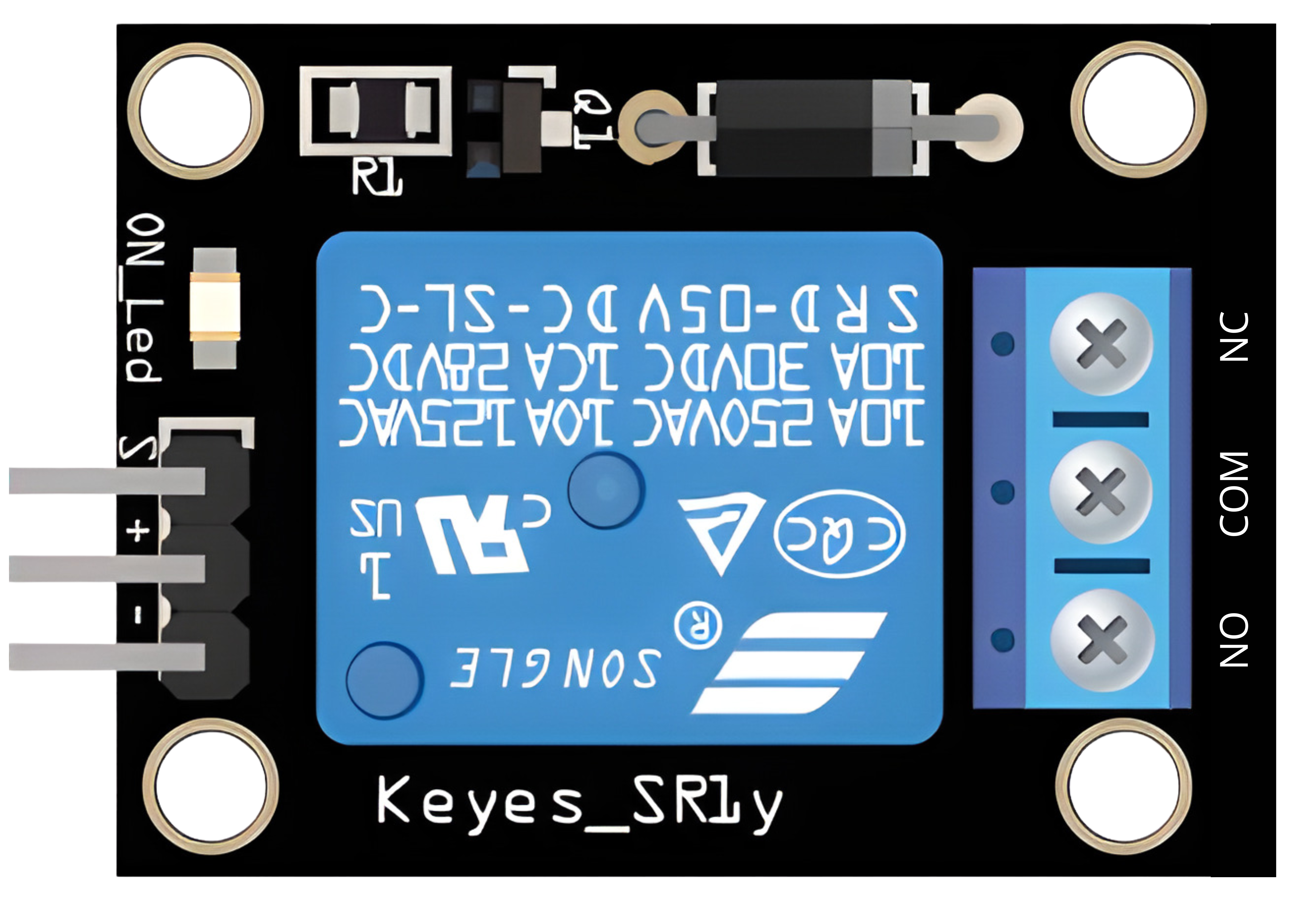
Pin Configuration and Descriptions

Pin Description
VCC Connect to the positive supply voltage (5V)
GND Connect to the ground of the power supply
IN Control signal input from the microcontroller
NO Normally Open: Relay is disconnected by default, closes when activated
COM Common: Connects to the circuit to be controlled
NC Normally Closed: Relay is connected by default, opens when activated

Usage Instructions

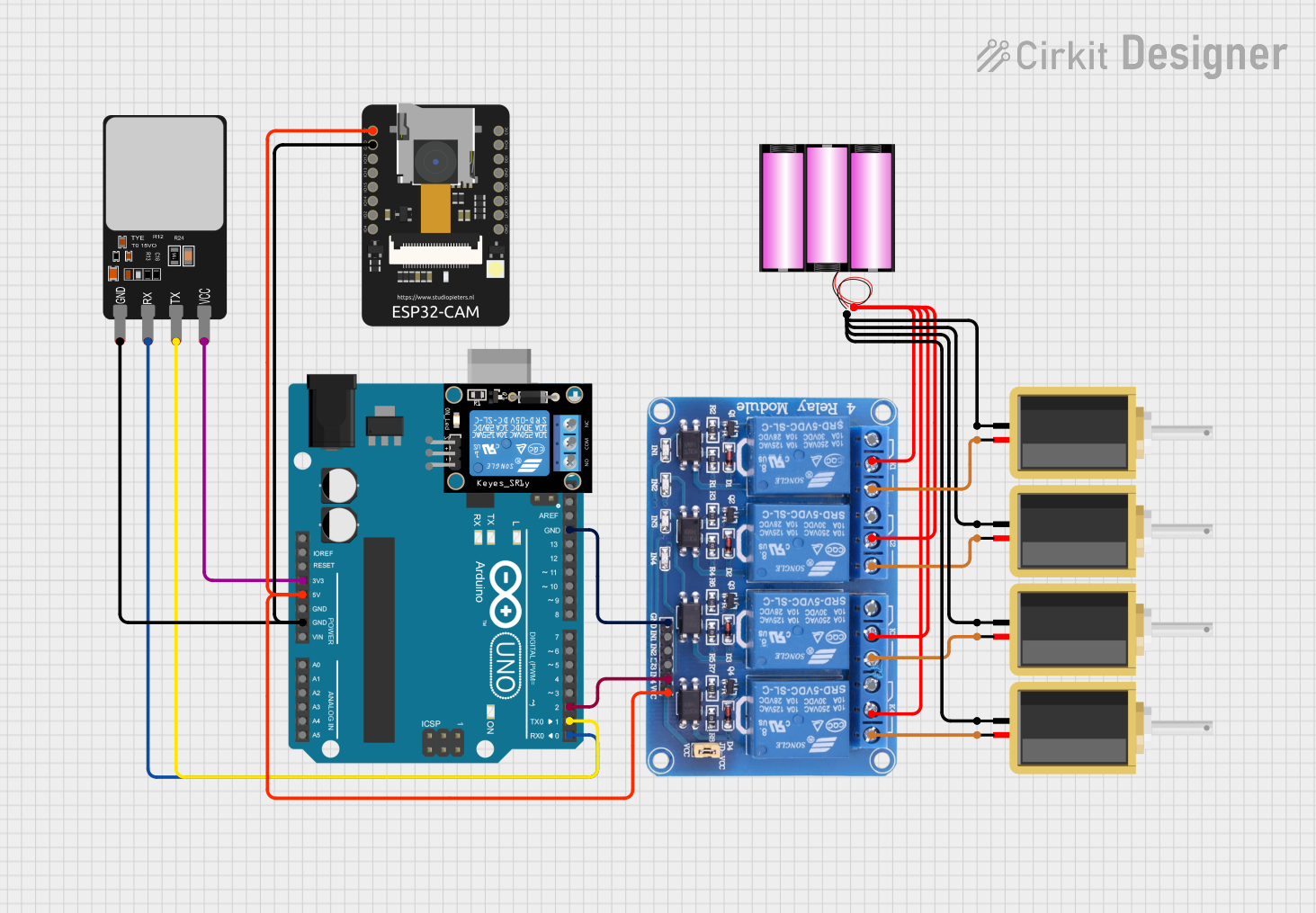
How to Use the Component in a Circuit

  1. Connect the VCC pin to a 5V power supply.
  2. Connect the GND pin to the ground of the power supply.
  3. Connect the IN pin to a digital output pin of a microcontroller.
  4. Connect the device you want to control to the NO or NC and COM pins, depending on whether you want the device to be powered when the relay is activated (NO) or deactivated (NC).

Important Considerations and Best Practices

  • Ensure that the power ratings of the relay match the requirements of the controlled device.
  • Do not exceed the maximum voltage and current ratings of the relay.
  • Use a flyback diode when controlling inductive loads to prevent back EMF damage.
  • Isolate the control circuit from the high-power circuit to prevent electrical noise and interference.
  • Always ensure proper safety measures when dealing with high voltage or current.

Example Code for Arduino UNO

// Define the relay control pin
const int relayPin = 2;

void setup() {
  // Set the relay pin as an OUTPUT
  pinMode(relayPin, OUTPUT);
}

void loop() {
  // Turn on the relay (activate the connected device)
  digitalWrite(relayPin, HIGH);
  delay(1000); // Wait for 1 second
  
  // Turn off the relay (deactivate the connected device)
  digitalWrite(relayPin, LOW);
  delay(1000); // Wait for 1 second
}

Troubleshooting and FAQs

Common Issues Users Might Face

  • Relay does not switch: Check the control signal and power supply connections.
  • Intermittent operation: Ensure stable power supply and check for loose connections.
  • Clicking sound but no action: Verify that the load does not exceed the relay's ratings.

Solutions and Tips for Troubleshooting

  • Double-check wiring, especially the control signal and power supply.
  • Measure the control signal voltage to ensure it is within TTL levels.
  • Use a multimeter to check the continuity of the relay contacts in both states.
  • Ensure that the code uploaded to the microcontroller is correct and that the correct pin is being used.

FAQs

Q: Can I control the relay module with a 3.3V signal? A: Some relay modules can be triggered with 3.3V, but it's essential to check the specifications of your specific module.

Q: Is it safe to control AC devices with a relay module? A: Yes, as long as the device's power requirements do not exceed the relay's ratings and proper safety precautions are taken.

Q: Can I use PWM to control the relay? A: No, relays require a stable HIGH or LOW signal to switch states. PWM is not suitable for relay control.

Remember to always follow safety guidelines when working with electronics, especially when controlling high-power devices.