
How to Use Fan 3: Examples, Pinouts, and Specs
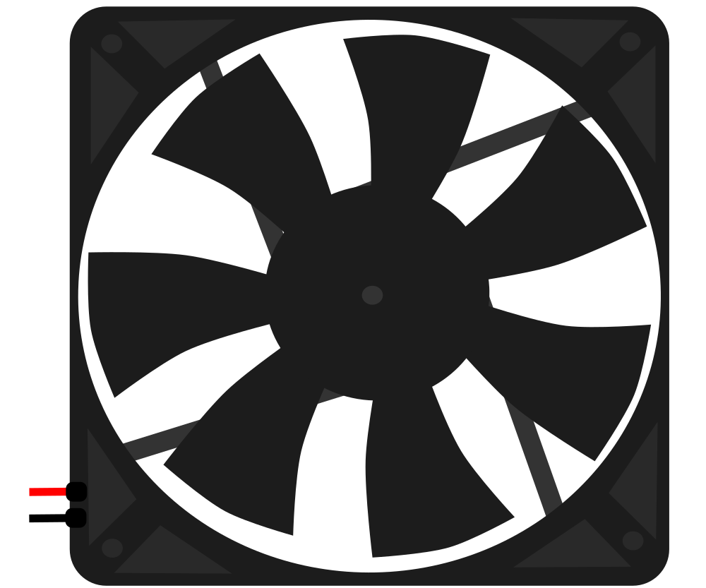
 Design with Fan 3 in Cirkit Designer
Introduction
The Fan 3 is a compact and efficient device designed to create airflow for cooling or ventilation purposes. It is commonly used in electronic enclosures, computer systems, and other applications where heat dissipation is critical. By maintaining optimal airflow, the Fan 3 helps prevent overheating and ensures the longevity and reliability of electronic components.
Explore Projects Built with Fan 3
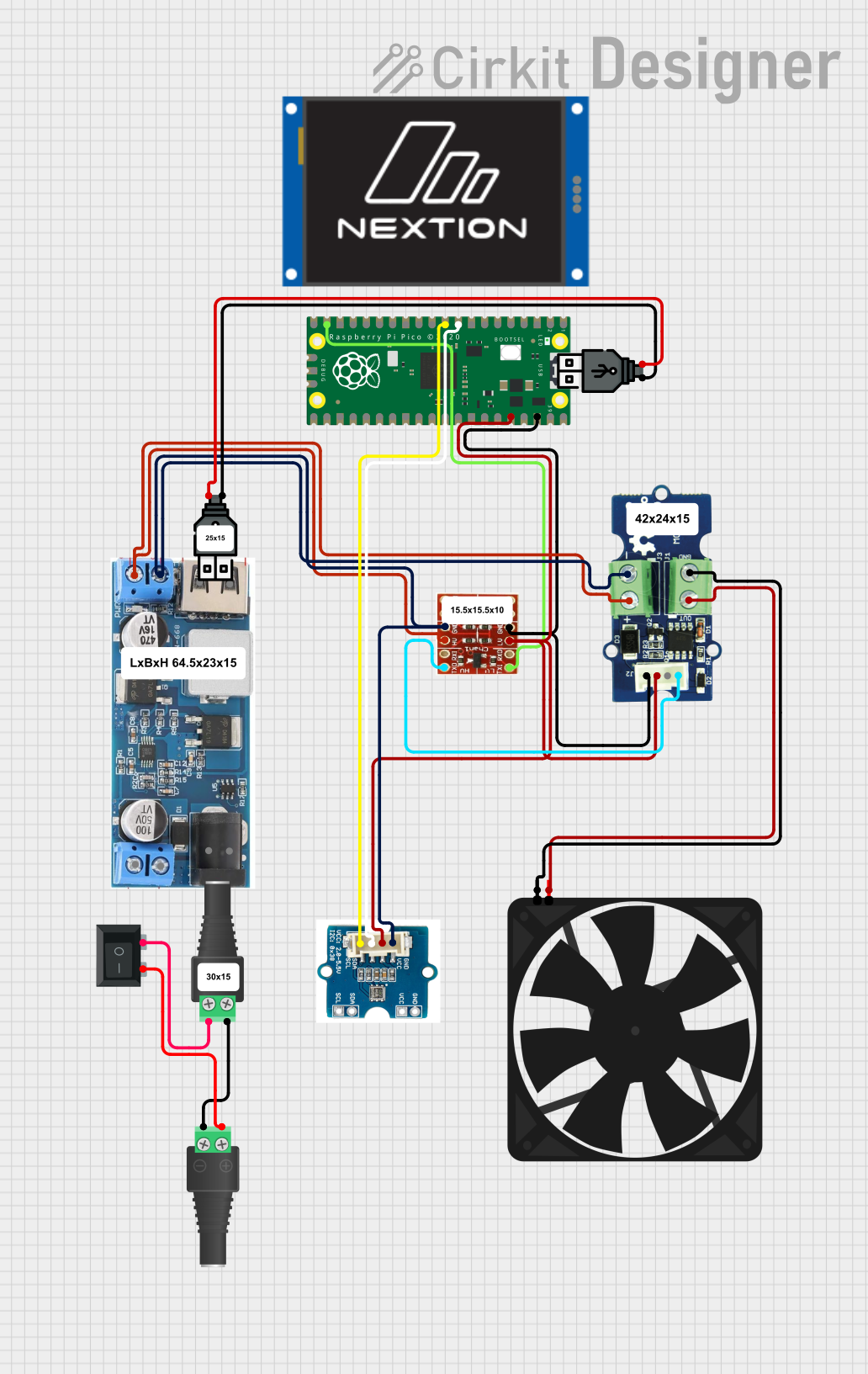 Open Project in Cirkit Designer
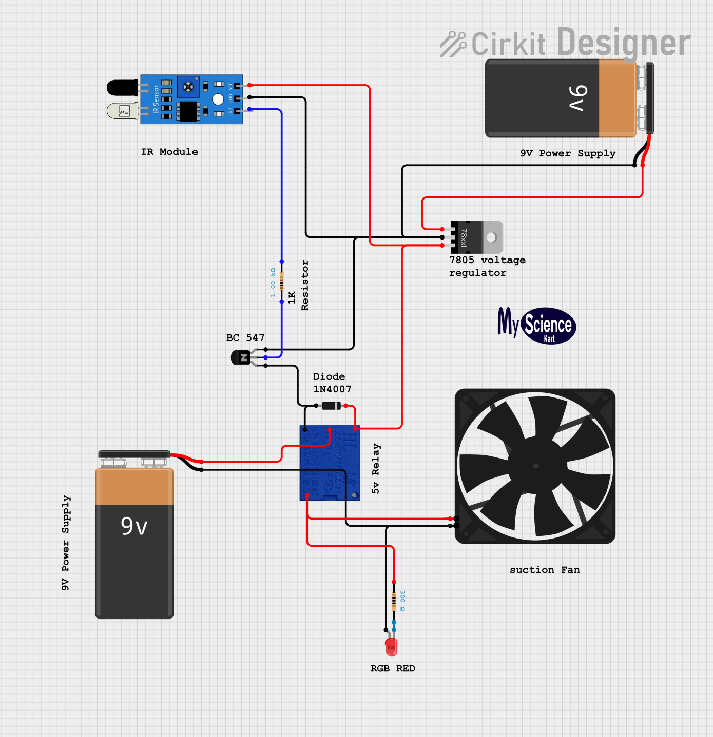 Open Project in Cirkit Designer
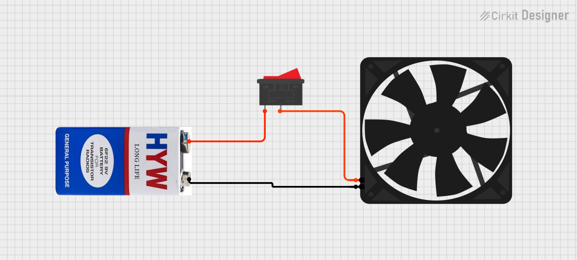 Open Project in Cirkit Designer
 Open Project in Cirkit Designer
Explore Projects Built with Fan 3
Open Project in Cirkit DesignerOpen Project in Cirkit DesignerOpen Project in Cirkit DesignerOpen Project in Cirkit DesignerCommon Applications:
- Cooling electronic enclosures and circuit boards
- Ventilating small spaces or devices
- Enhancing airflow in 3D printers, power supplies, and robotics
- General-purpose cooling in DIY electronics projects
Technical Specifications
Key Specifications:
| Parameter | Value |
|---|---|
| Operating Voltage | 5V DC |
| Operating Current | 0.2A |
| Power Consumption | 1W |
| Airflow | 10 CFM (Cubic Feet per Minute) |
| Dimensions | 40mm x 40mm x 10mm |
| Connector Type | 2-pin JST or bare wires |
| Noise Level | 25 dBA |
| Bearing Type | Sleeve Bearing |
| Lifespan | 30,000 hours at 25°C |
Pin Configuration:
| Pin Number | Wire Color | Description |
|---|---|---|
| 1 | Red | Positive Voltage (VCC) |
| 2 | Black | Ground (GND) |
Usage Instructions
How to Use the Fan 3 in a Circuit:
- Power Supply: Ensure the Fan 3 is connected to a stable 5V DC power source. Exceeding the voltage rating may damage the fan.
- Wiring: Connect the red wire to the positive terminal (VCC) and the black wire to the ground (GND) of your power supply or circuit.
- Mounting: Secure the fan using screws or adhesive mounts to ensure proper airflow direction. The airflow direction is typically indicated by an arrow on the fan housing.
- Polarity Check: Double-check the wiring polarity before powering the fan to avoid damage.
Important Considerations:
- Airflow Direction: Ensure the fan is oriented correctly to direct airflow where it is needed. The side with the fan blades typically pulls air in, while the opposite side pushes air out.
- Noise Reduction: To minimize noise, mount the fan on vibration-dampening pads or use rubber grommets.
- Heat Management: Avoid obstructing the airflow path to maximize cooling efficiency.
- Arduino Compatibility: The Fan 3 can be controlled using an Arduino UNO with a transistor or MOSFET for switching. A PWM signal can be used to adjust the fan speed.
Example Arduino Code:
// Example code to control Fan 3 speed using PWM on Arduino UNO
// Connect the fan's positive wire to a 5V power source and the negative wire
// to the collector of an NPN transistor. The emitter should be connected to GND.
// The base of the transistor should be connected to a PWM pin via a resistor.

const int fanPin = 9; // PWM pin connected to the transistor base
int fanSpeed = 128;   // Fan speed (0-255, where 255 is full speed)

void setup() {
  pinMode(fanPin, OUTPUT); // Set the fan pin as an output
}

void loop() {
  analogWrite(fanPin, fanSpeed); // Set fan speed using PWM
  delay(1000);                  // Keep the fan running at this speed for 1 second

  // Example: Gradually increase fan speed
  for (fanSpeed = 0; fanSpeed <= 255; fanSpeed += 5) {
    analogWrite(fanPin, fanSpeed); // Update fan speed
    delay(100);                   // Wait 100ms between speed changes
  }

  // Example: Gradually decrease fan speed
  for (fanSpeed = 255; fanSpeed >= 0; fanSpeed -= 5) {
    analogWrite(fanPin, fanSpeed); // Update fan speed
    delay(100);                   // Wait 100ms between speed changes
  }
}
Troubleshooting and FAQs
Common Issues:
Fan Not Spinning:
- Cause: Incorrect wiring or insufficient power supply.
- Solution: Verify the wiring connections and ensure the power supply provides 5V DC.
Excessive Noise:
- Cause: Loose mounting or worn-out bearings.
- Solution: Secure the fan properly and consider replacing it if the bearings are worn.
Overheating Components:
- Cause: Insufficient airflow or obstructed vents.
- Solution: Check for obstructions and ensure the fan is oriented correctly.
Fan Speed Not Changing with PWM:
- Cause: Incorrect transistor or wiring setup.
- Solution: Verify the transistor connections and ensure the PWM pin is configured correctly.
FAQs:
Can I run the Fan 3 at 12V? No, the Fan 3 is designed for 5V DC operation. Running it at 12V may damage the motor.
How do I clean the fan? Use compressed air to remove dust and debris. Avoid using liquids or disassembling the fan.
Can I use the Fan 3 without a microcontroller? Yes, you can connect it directly to a 5V power source for constant operation.
What is the maximum operating temperature? The Fan 3 can operate reliably in temperatures up to 70°C.