How to Use Fly Sky Receiver: Examples, Pinouts, and Specs
Introduction
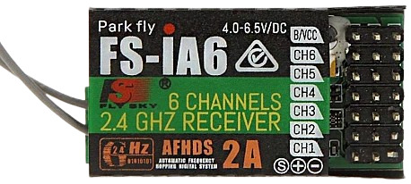
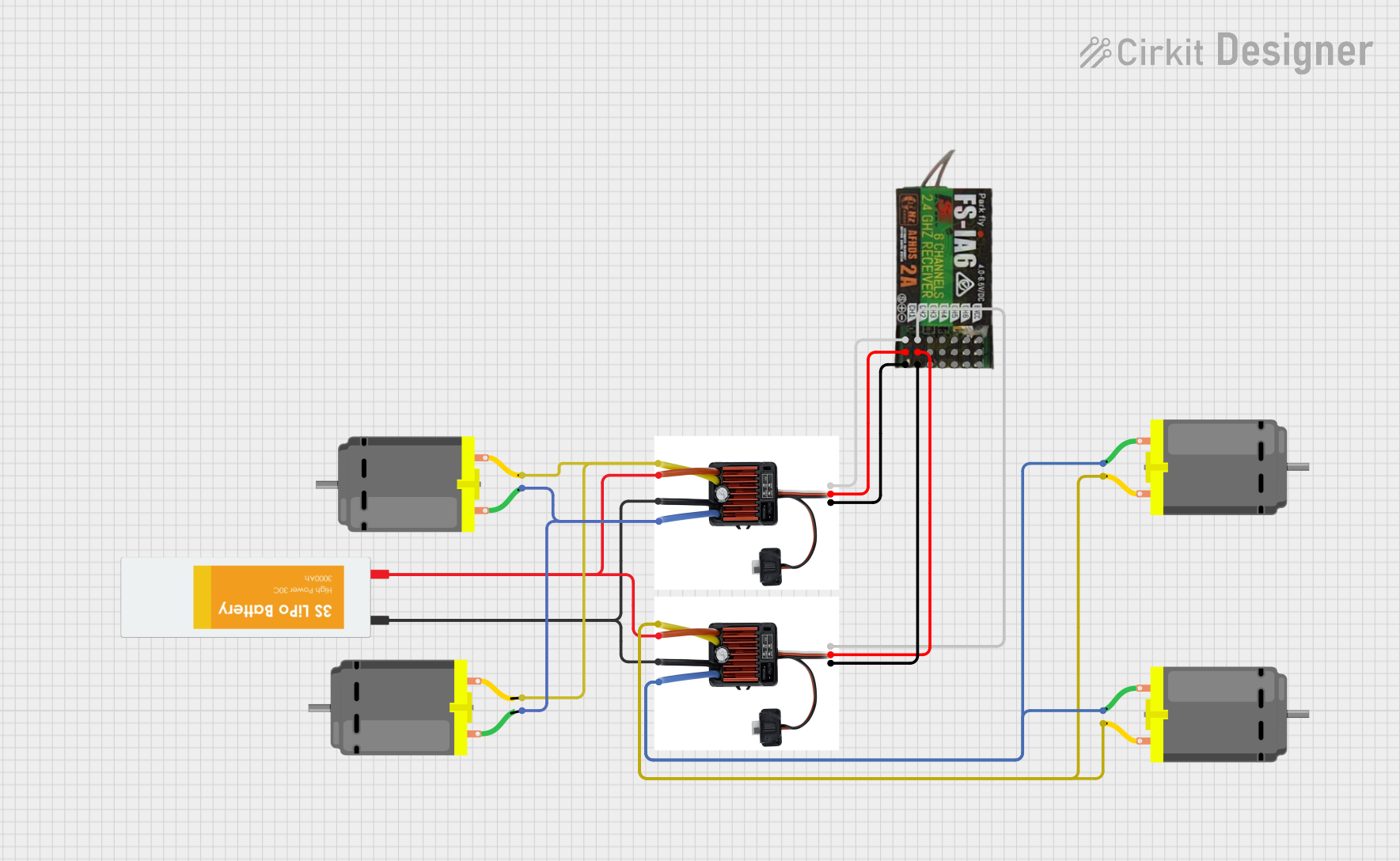
The Fly Sky Receiver is a radio receiver used in remote control systems, typically for drones, RC cars, and other remote-controlled devices. It receives signals from a Fly Sky transmitter and converts them into control signals for the device. This component is essential for ensuring reliable communication between the transmitter and the controlled device, enabling precise control and maneuverability.
Explore Projects Built with Fly Sky Receiver
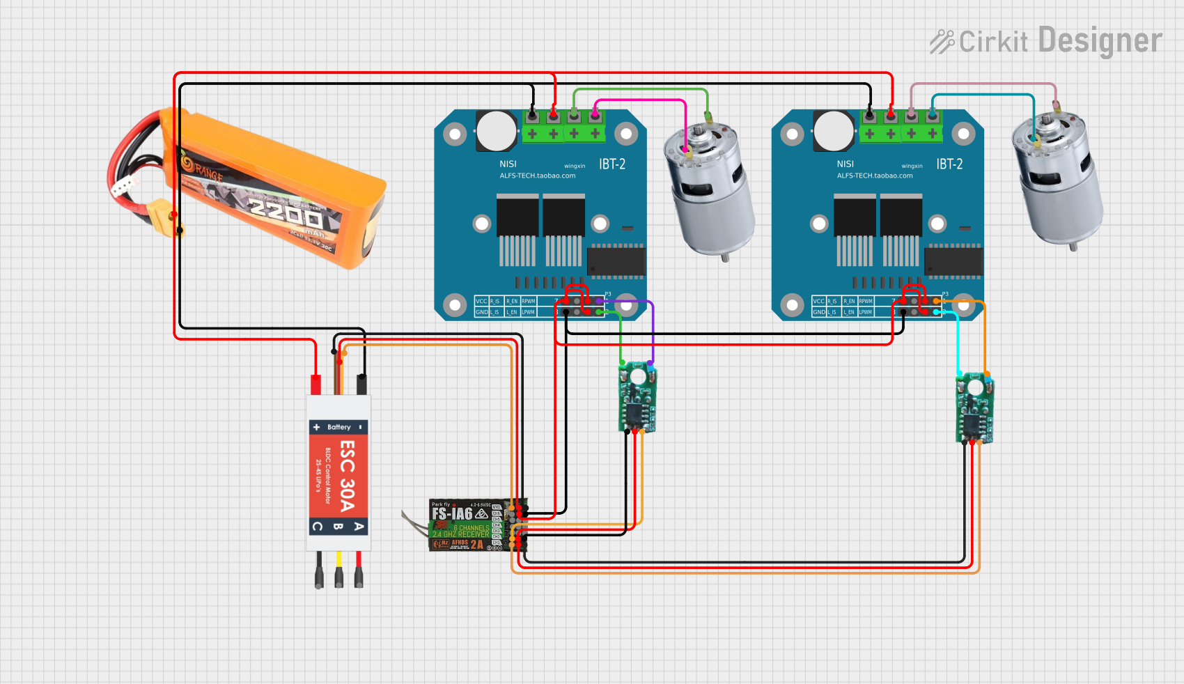
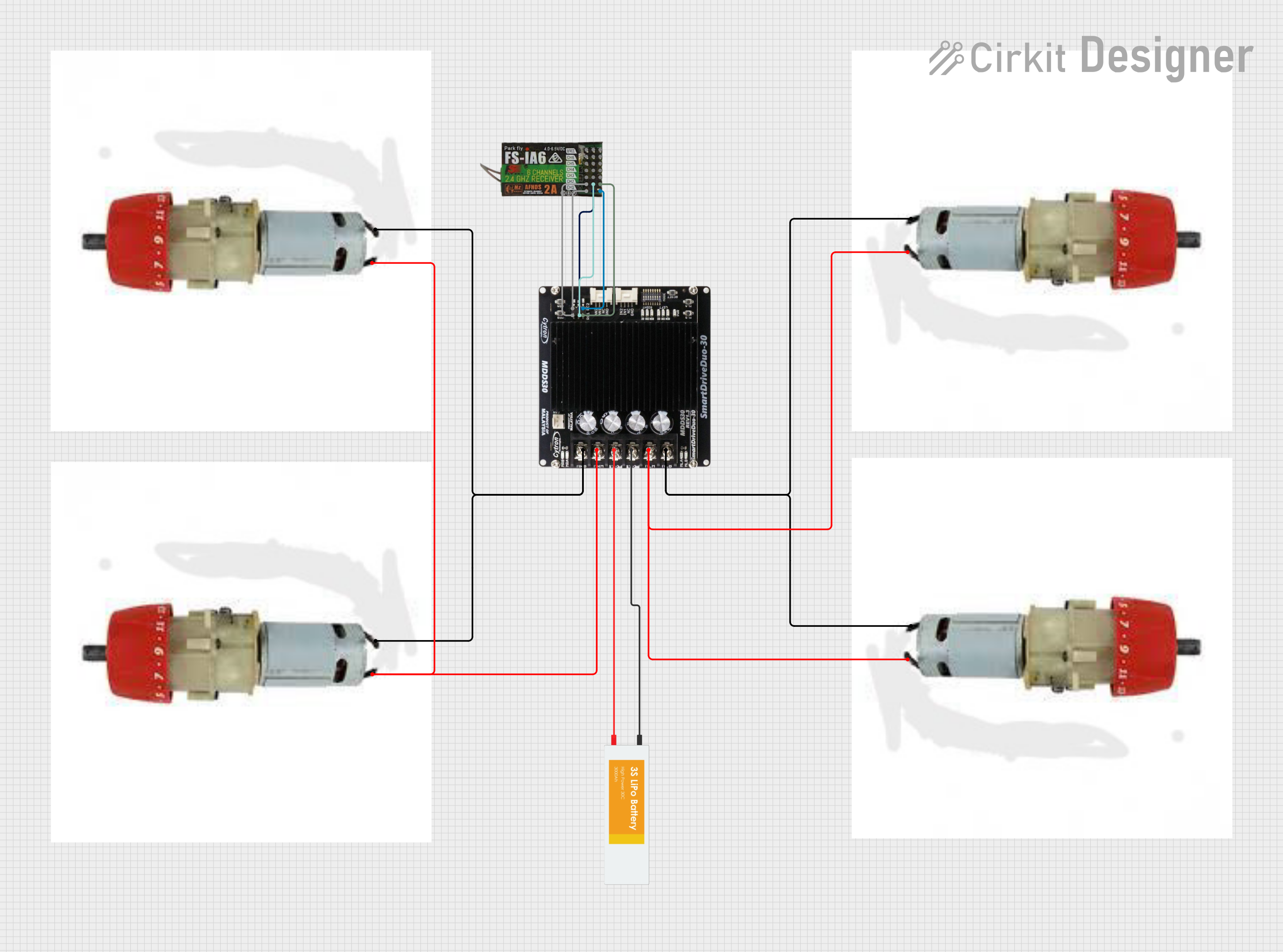
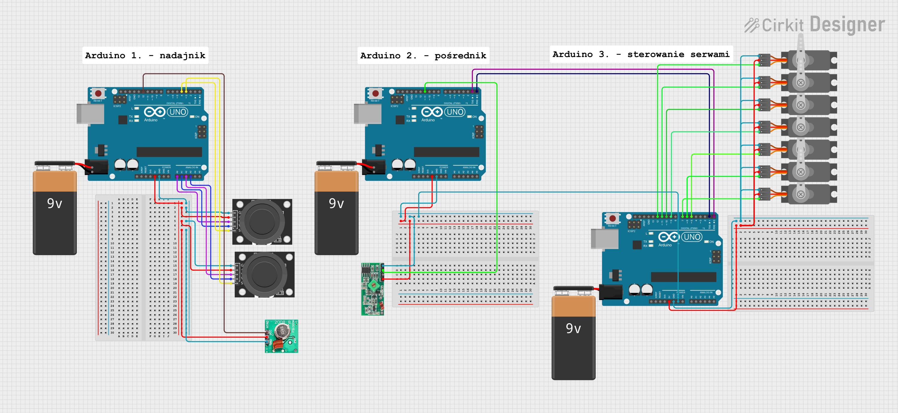
Explore Projects Built with Fly Sky Receiver
Technical Specifications
Key Technical Details
| Specification | Value |
|---|---|
| Operating Voltage | 4.0 - 6.5V |
| Operating Current | 30mA @ 5V |
| Frequency Range | 2.405 - 2.475GHz |
| Number of Channels | 6, 8, or 10 (depending on model) |
| Modulation Type | GFSK |
| Sensitivity | -105dBm |
| Dimensions | 40mm x 21mm x 7mm |
| Weight | 10g |
Pin Configuration and Descriptions
| Pin Number | Pin Name | Description |
|---|---|---|
| 1 | VCC | Power supply input (4.0 - 6.5V) |
| 2 | GND | Ground |
| 3 | CH1 | Channel 1 signal output |
| 4 | CH2 | Channel 2 signal output |
| 5 | CH3 | Channel 3 signal output |
| 6 | CH4 | Channel 4 signal output |
| 7 | CH5 | Channel 5 signal output |
| 8 | CH6 | Channel 6 signal output |
| 9 | BIND | Binding button for pairing with transmitter |
Usage Instructions
How to Use the Fly Sky Receiver in a Circuit
- Power Connection: Connect the VCC pin to a 5V power supply and the GND pin to the ground of your circuit.
- Channel Connections: Connect the CH1 to CH6 pins to the corresponding control inputs of your device (e.g., motor controllers, servos).
- Binding: To pair the receiver with a Fly Sky transmitter, press and hold the BIND button while powering on the receiver. Follow the transmitter's binding procedure to complete the pairing process.
Important Considerations and Best Practices
- Antenna Placement: Ensure the antenna is placed away from metal objects and other electronic components to avoid interference.
- Power Supply: Use a stable power supply within the specified voltage range to prevent damage to the receiver.
- Signal Integrity: Keep signal wires as short as possible and avoid running them parallel to power lines to minimize noise and interference.
Example Code for Arduino UNO
Below is an example code to read signals from the Fly Sky Receiver using an Arduino UNO. This example reads the PWM signals from Channel 1 and prints the pulse width to the Serial Monitor.
// Fly Sky Receiver - Arduino UNO Example Code
// This code reads the PWM signal from Channel 1 and prints the pulse width
// to the Serial Monitor.

const int ch1Pin = 2; // Channel 1 connected to digital pin 2

void setup() {
  Serial.begin(9600); // Initialize serial communication at 9600 baud
  pinMode(ch1Pin, INPUT); // Set Channel 1 pin as input
}

void loop() {
  // Read the pulse width from Channel 1
  unsigned long pulseWidth = pulseIn(ch1Pin, HIGH);

  // Print the pulse width to the Serial Monitor
  Serial.print("Channel 1 Pulse Width: ");
  Serial.println(pulseWidth);

  delay(100); // Wait for 100 milliseconds before the next reading
}
Troubleshooting and FAQs
Common Issues and Solutions
No Signal Received:
- Solution: Ensure the receiver is properly powered and the transmitter is turned on and bound to the receiver.
Interference or Unstable Signal:
- Solution: Check the antenna placement and ensure it is away from metal objects and other electronic components. Verify that the power supply is stable and within the specified voltage range.
Binding Issues:
- Solution: Follow the binding procedure carefully. Ensure the BIND button is pressed and held while powering on the receiver. Check the transmitter's manual for specific binding instructions.
FAQs
Q1: Can I use the Fly Sky Receiver with other brands of transmitters?
- A1: The Fly Sky Receiver is designed to work specifically with Fly Sky transmitters. Compatibility with other brands is not guaranteed.
Q2: How do I know if the receiver is properly bound to the transmitter?
- A2: Most Fly Sky receivers have an LED indicator that shows the binding status. Refer to the receiver's manual for specific LED indications.
Q3: What is the maximum range of the Fly Sky Receiver?
- A3: The range depends on the specific model and environmental conditions. Generally, Fly Sky receivers have a range of up to 1km in open areas.
By following this documentation, users can effectively integrate the Fly Sky Receiver into their remote control systems, ensuring reliable and precise control of their devices.