How to Use STP16NF06 N-Channel Power MOSFET: Examples, Pinouts, and Specs
Introduction
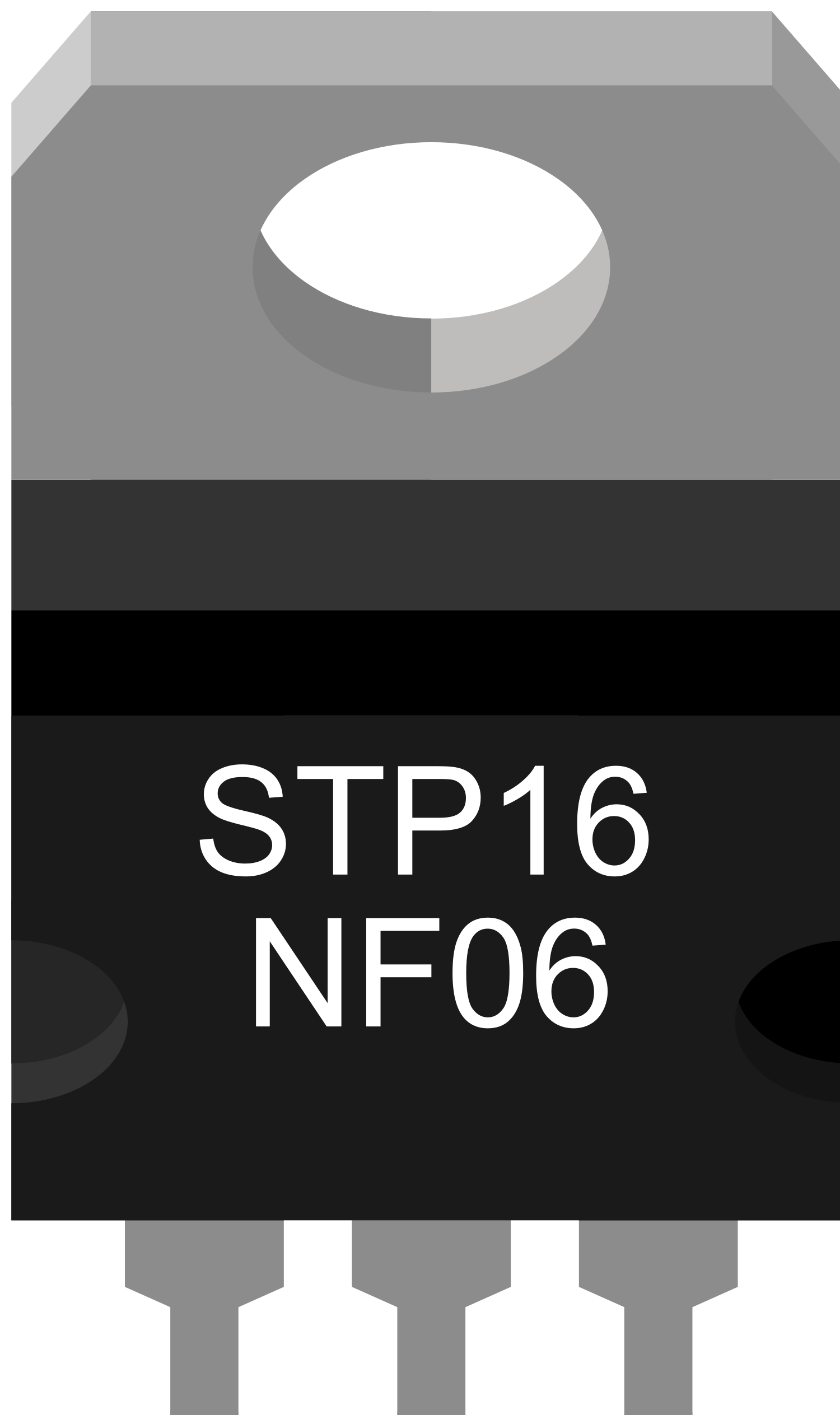
The STP16NF06 is an N-Channel Power MOSFET designed to handle high currents and high voltages, which makes it an ideal choice for applications requiring efficient power management and load switching. Its robustness and reliability are appreciated in motor control circuits, LED driving applications, power regulation modules, and various other high-power electronic systems.
Explore Projects Built with STP16NF06 N-Channel Power MOSFET
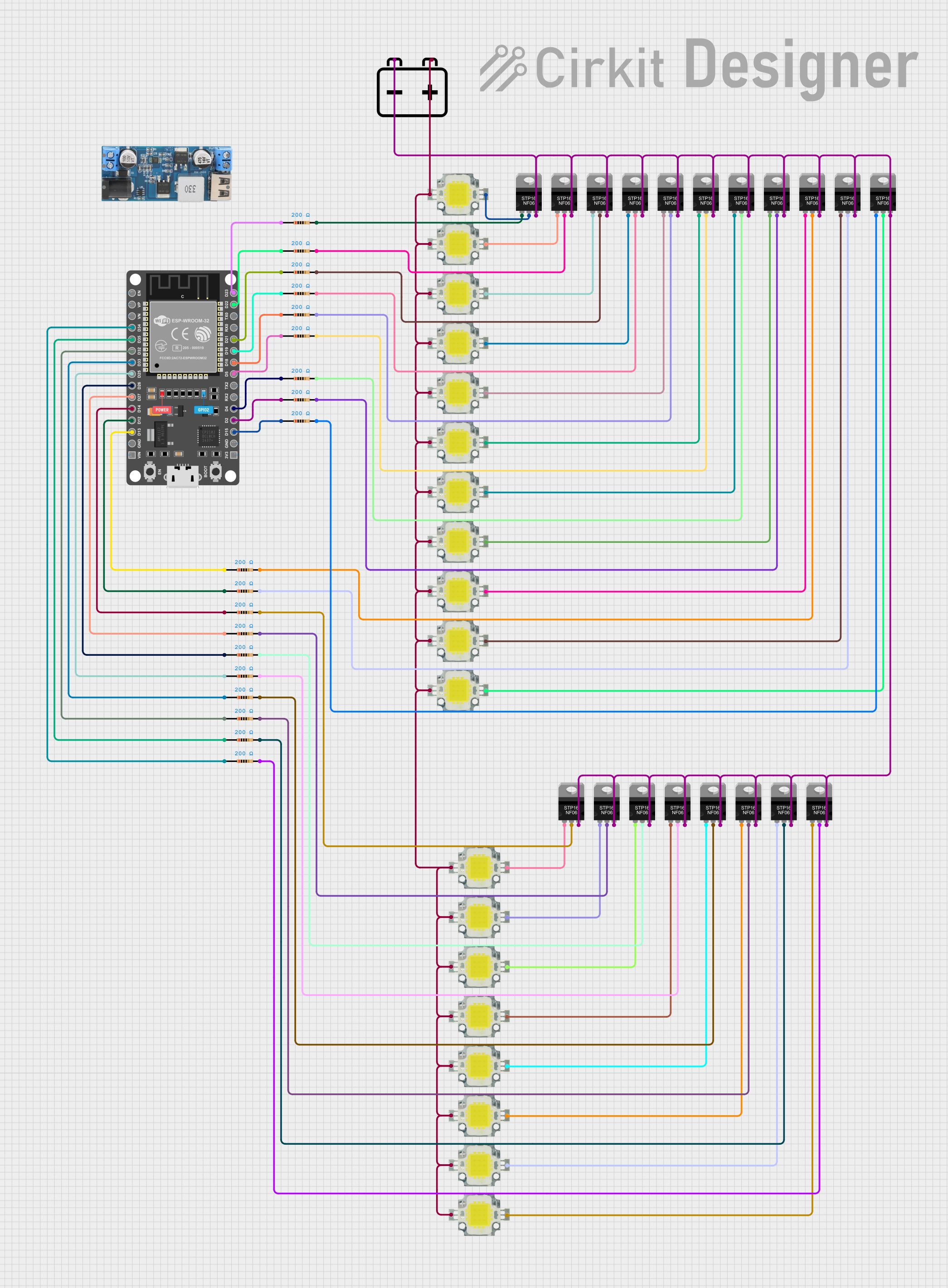

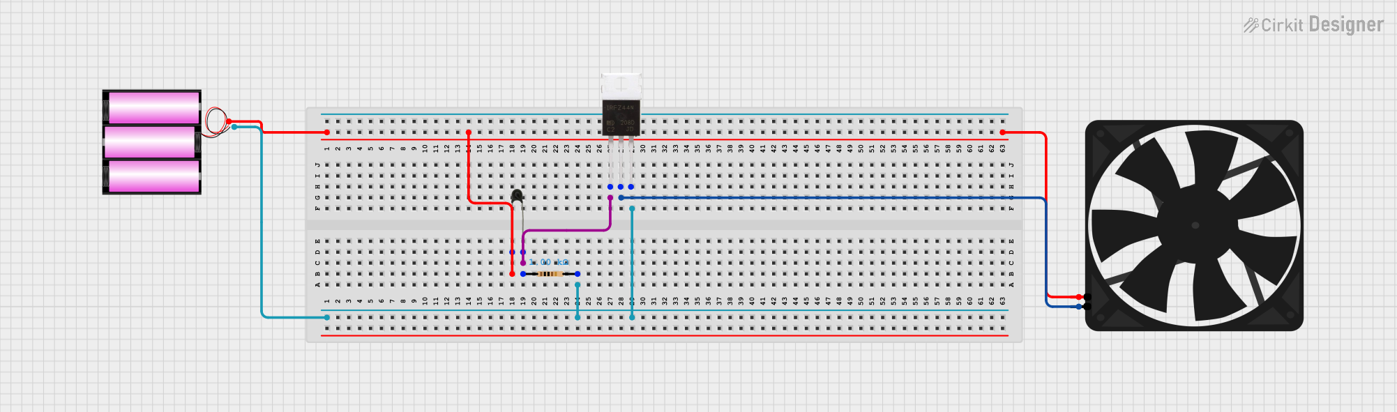
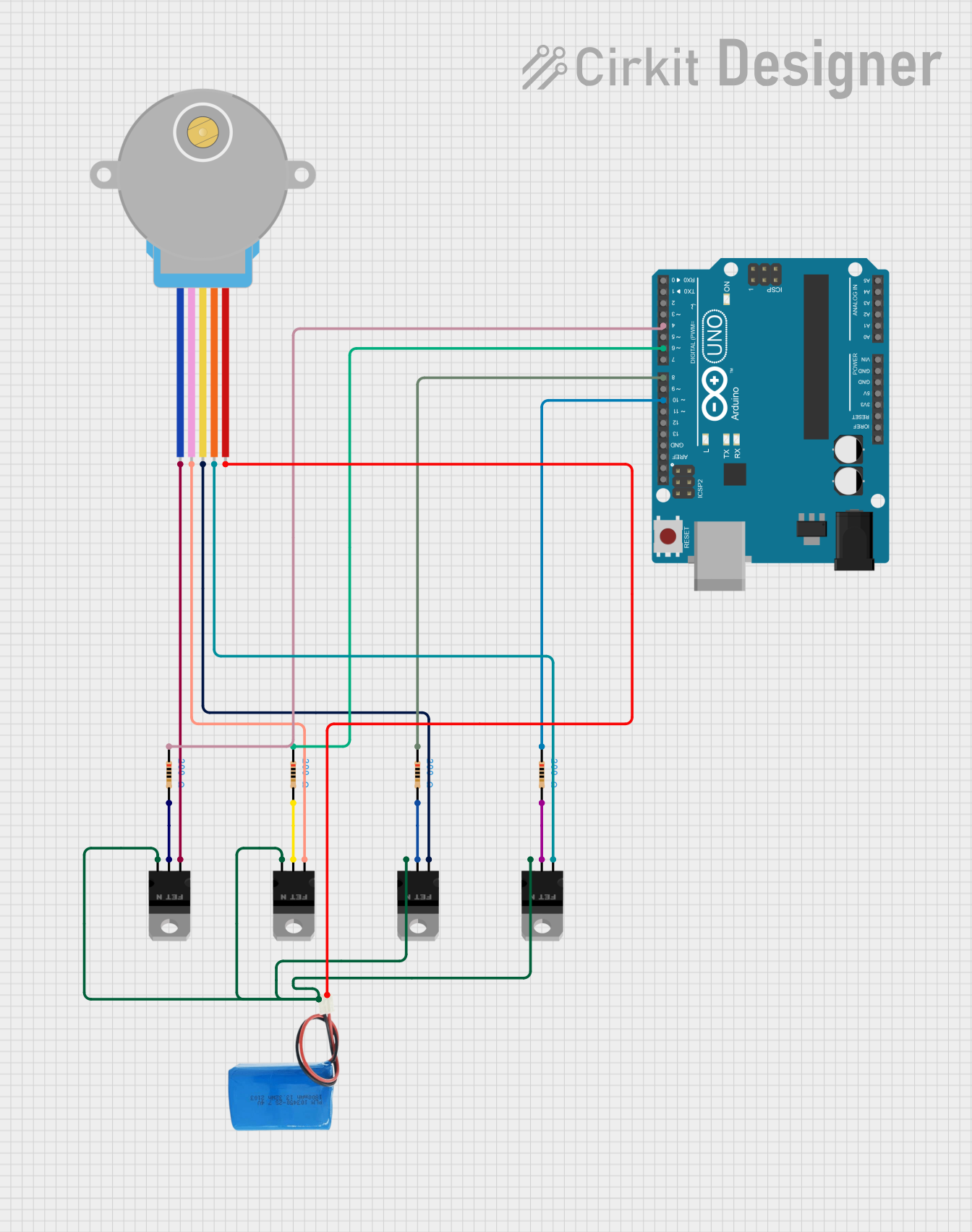
Explore Projects Built with STP16NF06 N-Channel Power MOSFET
Technical Specifications
Key Technical Details
- Drain-to-Source Voltage (Vdss): 60V
- Continuous Drain Current (Id): 16A
- Power Dissipation (Pd): 45W (Tc = 25°C)
- RDS(on): 0.1Ω (max)
- Gate Threshold Voltage (Vgs th): 2V to 4V
- Total Gate Charge (Qg): 17nC
Pin Configuration and Descriptions
| Pin Number | Name | Description |
|---|---|---|
| 1 | G | Gate |
| 2 | D | Drain |
| 3 | S | Source |
Usage Instructions
How to Use the STP16NF06 in a Circuit
Gate Drive: Apply a voltage between the gate (G) and source (S) to turn the MOSFET on. Ensure that this voltage is within the specified gate threshold voltage range.
Load Connection: Connect the load to the drain (D) terminal, and connect the source (S) terminal to the ground of the circuit.
Heat Management: Due to power dissipation during operation, ensure adequate heat sinking for the MOSFET to prevent overheating.
Protection: Use a flyback diode when switching inductive loads to prevent voltage spikes that could damage the MOSFET.
Best Practices
- Use a gate resistor to limit the inrush current to the gate and to dampen oscillations.
- Implement a pull-down resistor on the gate to ensure the MOSFET remains off when there is no driving voltage.
- Avoid exceeding the maximum voltage and current ratings to prevent damage to the MOSFET.
- Ensure proper PCB layout to minimize stray inductances and capacitances.
Troubleshooting and FAQs
Common Issues
- MOSFET Does Not Turn On: Check if the gate voltage is within the threshold range and if the gate resistor value is appropriate.
- MOSFET Overheating: Verify that the power dissipation is within limits and improve heat sinking if necessary.
- Unexpected Switching: Ensure there is no noise coupling into the gate and that the pull-down resistor is functioning.
Solutions and Tips
- If the MOSFET does not turn on, measure the gate voltage with respect to the source to confirm it's within the threshold.
- For overheating issues, recalculate the power dissipation and consider using a MOSFET with a higher current rating or better thermal management.
- To prevent unexpected switching, use proper PCB layout techniques and shield the gate from high-frequency noise sources.
FAQs
Q: Can I drive this MOSFET directly from a microcontroller? A: Yes, but ensure that the microcontroller can supply a gate voltage within the threshold range of the MOSFET.
Q: What is the purpose of the flyback diode in inductive load applications? A: The flyback diode provides a path for the inductive kickback when the MOSFET turns off, protecting it from voltage spikes.
Q: How can I improve the switching speed of the MOSFET? A: Use a gate driver to provide higher current to the gate, reducing the rise and fall times during switching.
Example Code for Arduino UNO
// Example code to control a high-power load with the STP16NF06 MOSFET
const int mosfetGatePin = 3; // Connect to the gate of the MOSFET

void setup() {
  pinMode(mosfetGatePin, OUTPUT);
}

void loop() {
  digitalWrite(mosfetGatePin, HIGH); // Turn on the MOSFET
  delay(1000);                        // Wait for 1 second
  digitalWrite(mosfetGatePin, LOW);  // Turn off the MOSFET
  delay(1000);                        // Wait for 1 second
}
Note: This example assumes that the Arduino can provide a suitable gate voltage for the STP16NF06. If the gate threshold voltage is higher than the Arduino output, a gate driver circuit will be required. Always ensure that the current and power ratings are within the limits of the MOSFET.