How to Use ESP-01 Adapter Module 3.3-5V: Examples, Pinouts, and Specs
Introduction
The ESP-01 Adapter Module 3.3-5V is a compact and efficient voltage regulator designed to simplify the integration of the ESP-01 Wi-Fi module into electronic projects. It converts a 5V input to the 3.3V required by the ESP-01, ensuring stable operation and protecting the module from overvoltage damage. This adapter is particularly useful for hobbyists and developers working with microcontrollers like Arduino or Raspberry Pi.
Explore Projects Built with ESP-01 Adapter Module 3.3-5V

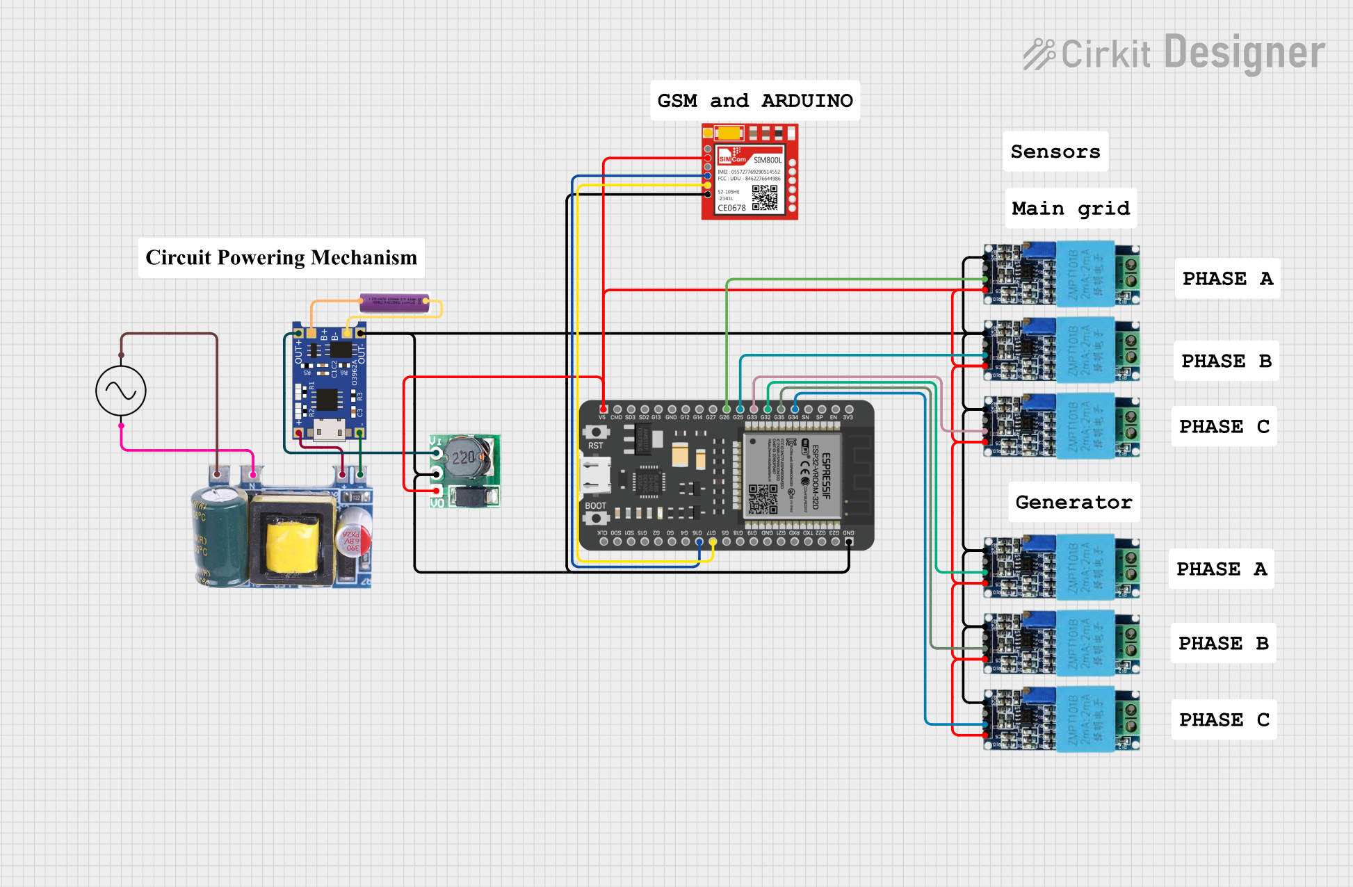


Explore Projects Built with ESP-01 Adapter Module 3.3-5V
Common Applications and Use Cases
- Powering the ESP-01 Wi-Fi module in IoT projects
- Simplifying connections between 5V microcontrollers and the ESP-01
- Prototyping wireless communication systems
- Home automation and smart devices
Technical Specifications
Key Technical Details
- Input Voltage: 5V DC
- Output Voltage: 3.3V DC
- Maximum Output Current: 500mA
- Dimensions: Approximately 25mm x 15mm
- Operating Temperature: -40°C to 85°C
- Compatibility: Designed specifically for the ESP-01 Wi-Fi module
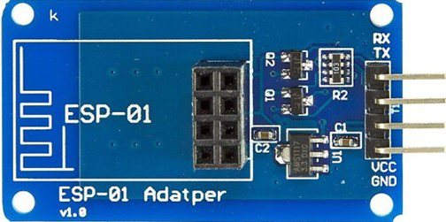
Pin Configuration and Descriptions
The ESP-01 Adapter Module has a simple pin layout for easy integration. Below is the pin configuration:
| Pin Name | Description |
|---|---|
| VCC | 5V input power supply |
| GND | Ground connection |
| TX | Transmit pin for serial communication (connected to ESP-01 TX) |
| RX | Receive pin for serial communication (connected to ESP-01 RX) |
| 3.3V | Regulated 3.3V output (used internally to power the ESP-01 module) |
Usage Instructions
How to Use the Component in a Circuit
Powering the Adapter:
- Connect the VCC pin of the adapter to a 5V power source (e.g., Arduino 5V pin or an external power supply).
- Connect the GND pin to the ground of your circuit.
Connecting the ESP-01:
- Insert the ESP-01 module into the adapter's socket. Ensure proper orientation to avoid damage.
- The adapter will automatically regulate the voltage to 3.3V for the ESP-01.
Serial Communication:
- Connect the TX pin of the adapter to the RX pin of your microcontroller.
- Connect the RX pin of the adapter to the TX pin of your microcontroller.
- Use a logic level shifter if your microcontroller operates at 3.3V to avoid signal mismatches.
Programming the ESP-01:
- To upload code to the ESP-01, use a USB-to-serial adapter or an Arduino configured as a programmer.
- Ensure the ESP-01 is in programming mode by pulling its GPIO0 pin low during reset.
Important Considerations and Best Practices
- Voltage Compatibility: Do not exceed 5V on the VCC pin, as this may damage the adapter or the ESP-01 module.
- Current Requirements: Ensure your power source can supply at least 500mA to avoid instability during Wi-Fi operations.
- Signal Levels: The adapter does not include logic level shifting for TX/RX pins. Use a level shifter if your microcontroller operates at 3.3V.
- Proper Orientation: Double-check the orientation of the ESP-01 module when inserting it into the adapter to prevent damage.
Example Code for Arduino UNO
Below is an example of how to use the ESP-01 with an Arduino UNO for basic communication:
#include <SoftwareSerial.h>

// Define software serial pins for communication with ESP-01
SoftwareSerial espSerial(2, 3); // RX, TX

void setup() {
  // Initialize serial communication with the ESP-01
  espSerial.begin(9600);
  Serial.begin(9600); // For debugging via Serial Monitor

  // Send a test command to the ESP-01
  espSerial.println("AT");
}

void loop() {
  // Check if the ESP-01 has sent any data
  if (espSerial.available()) {
    String response = espSerial.readString();
    Serial.println("ESP-01 Response: " + response); // Print response to Serial Monitor
  }

  // Check if the user has sent any data via Serial Monitor
  if (Serial.available()) {
    String command = Serial.readString();
    espSerial.println(command); // Send command to ESP-01
  }
}
Troubleshooting and FAQs
Common Issues and Solutions
ESP-01 Not Responding:
- Cause: Incorrect wiring or insufficient power supply.
- Solution: Double-check all connections and ensure the power source can supply at least 500mA.
Overheating:
- Cause: Prolonged operation at high current or incorrect input voltage.
- Solution: Ensure the input voltage is 5V and avoid overloading the ESP-01.
Serial Communication Fails:
- Cause: Mismatched baud rate or incorrect TX/RX connections.
- Solution: Verify the baud rate (default is 9600 for most ESP-01 modules) and ensure TX/RX pins are correctly connected.
ESP-01 Not Entering Programming Mode:
- Cause: GPIO0 not pulled low during reset.
- Solution: Connect GPIO0 to GND and reset the ESP-01 before uploading code.
FAQs
Can I use the adapter with other 3.3V modules?
- Yes, but ensure the module's current requirements do not exceed 500mA.
Do I need a separate logic level shifter for TX/RX?
- If your microcontroller operates at 5V, the adapter can handle it. For 3.3V microcontrollers, a level shifter is recommended.
What is the maximum distance for serial communication?
- For reliable communication, keep the distance under 1 meter. Use shielded cables for longer distances.
This documentation provides a comprehensive guide to using the ESP-01 Adapter Module 3.3-5V effectively in your projects.