How to Use Potentiometer: Examples, Pinouts, and Specs

Introduction
A potentiometer is a three-terminal variable resistor that allows users to adjust voltage levels in a circuit. By varying its resistance, it can control current flow and signal levels, making it a versatile component in electronic designs. Potentiometers are commonly used for tasks such as adjusting volume in audio equipment, tuning circuits, and controlling brightness in displays.
Explore Projects Built with Potentiometer
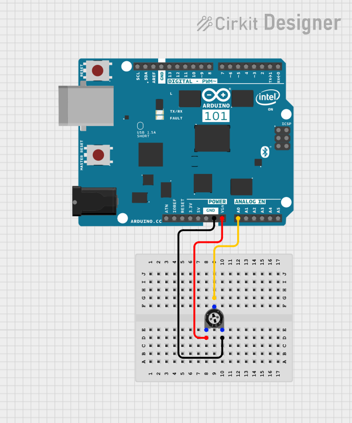
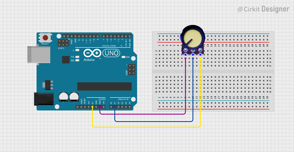
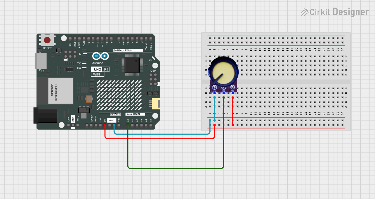
Explore Projects Built with Potentiometer
Common Applications and Use Cases
- Volume control in audio devices
- Brightness adjustment in LED circuits
- Tuning and calibration in electronic circuits
- Position sensing in joysticks and rotary encoders
- Signal level adjustment in amplifiers
Technical Specifications
Below are the general technical specifications for a standard potentiometer. Note that specific values may vary depending on the model and manufacturer.
| Parameter | Specification |
|---|---|
| Resistance Range | 1 kΩ to 1 MΩ (common values: 10 kΩ, 100 kΩ) |
| Power Rating | 0.1 W to 1 W |
| Tolerance | ±10% to ±20% |
| Operating Voltage | Up to 50 V (varies by model) |
| Rotation Angle | 270° (typical for rotary potentiometers) |
| Temperature Range | -40°C to +125°C |
Pin Configuration and Descriptions
A potentiometer typically has three pins:
| Pin | Description |
|---|---|
| Pin 1 | Connected to one end of the resistive track (fixed voltage or ground) |
| Pin 2 | Wiper (variable output voltage based on rotation/position) |
| Pin 3 | Connected to the other end of the resistive track (fixed voltage or ground) |
Usage Instructions
How to Use the Potentiometer in a Circuit
Connect the Fixed Terminals (Pins 1 and 3):
- Pin 1 is usually connected to ground (GND).
- Pin 3 is connected to the supply voltage (e.g., 5V or 3.3V).
Connect the Wiper (Pin 2):
- Pin 2 provides the variable voltage output. Connect this pin to the input of the circuit where you need adjustable voltage.
Adjust the Resistance:
- Rotate the potentiometer knob or slider to change the resistance and adjust the output voltage.
Important Considerations and Best Practices
- Power Rating: Ensure the potentiometer's power rating is not exceeded to avoid overheating or damage.
- Debouncing: When used in digital circuits, consider adding a capacitor to smooth out noise caused by mechanical movement.
- Mounting: Use a potentiometer with a suitable form factor (e.g., rotary, slide) for your application.
- Voltage Limits: Do not exceed the maximum voltage rating of the potentiometer.
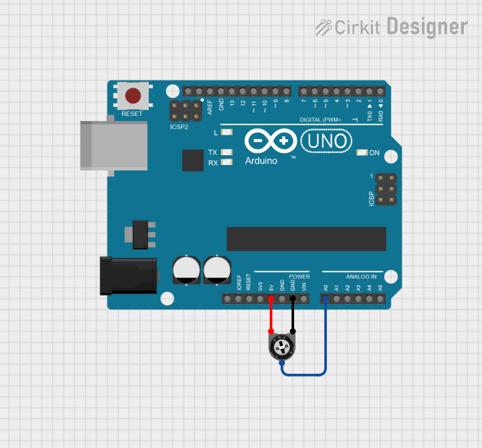
Example: Using a Potentiometer with Arduino UNO
Below is an example of how to use a 10 kΩ potentiometer to read analog values with an Arduino UNO.
// Example: Reading a potentiometer value with Arduino UNO
// Connect Pin 1 of the potentiometer to GND, Pin 3 to 5V, and Pin 2 to A0.

const int potPin = A0; // Pin connected to the potentiometer wiper
int potValue = 0;      // Variable to store the potentiometer value

void setup() {
  Serial.begin(9600); // Initialize serial communication
}

void loop() {
  potValue = analogRead(potPin); // Read the analog value (0-1023)
  Serial.print("Potentiometer Value: ");
  Serial.println(potValue); // Print the value to the Serial Monitor
  delay(100); // Small delay for stability
}
Troubleshooting and FAQs
Common Issues and Solutions
No Output Voltage:
- Cause: Incorrect wiring of the potentiometer pins.
- Solution: Verify that Pin 1 is connected to GND, Pin 3 to the supply voltage, and Pin 2 to the circuit input.
Inconsistent or Noisy Output:
- Cause: Dust or wear on the resistive track.
- Solution: Clean the potentiometer with contact cleaner or replace it if worn out.
Overheating:
- Cause: Exceeding the power rating of the potentiometer.
- Solution: Use a potentiometer with a higher power rating or reduce the current through the component.
Limited Adjustment Range:
- Cause: Incorrect resistance value for the application.
- Solution: Select a potentiometer with a resistance range suitable for your circuit.
FAQs
Q: Can I use a potentiometer to control an LED's brightness?
A: Yes, connect the potentiometer to a PWM pin on a microcontroller or use it to adjust the input voltage to the LED circuit.Q: What is the difference between a linear and logarithmic potentiometer?
A: A linear potentiometer changes resistance uniformly, while a logarithmic potentiometer changes resistance exponentially, often used in audio applications.Q: Can I use a potentiometer as a variable resistor?
A: Yes, by connecting only two pins (one fixed terminal and the wiper), you can use it as a variable resistor.
By following this documentation, you can effectively integrate a potentiometer into your electronic projects!