Cirkit Designer Logo
Cirkit Designer
Your all-in-one circuit design IDE
Home / 
Component Documentation

How to Use С2000-КДЛ-2И исп.01: Examples, Pinouts, and Specs

Image of С2000-КДЛ-2И исп.01
Cirkit Designer LogoDesign with С2000-КДЛ-2И исп.01 in Cirkit Designer

Introduction

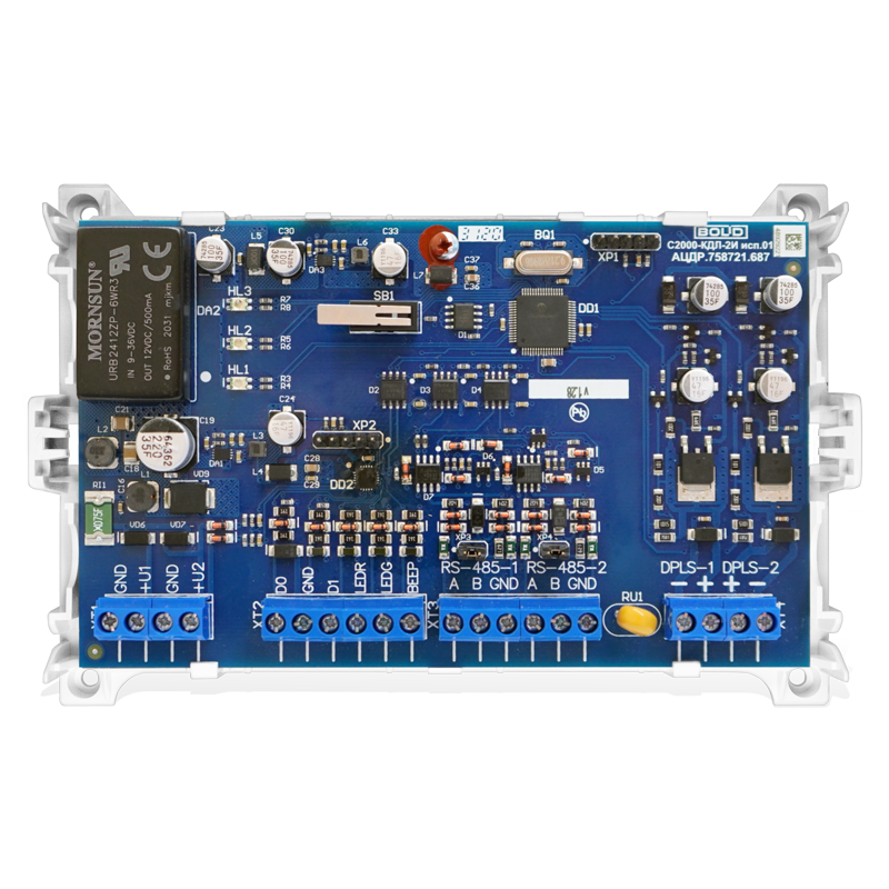
The С2000-КДЛ-2И исп.01, manufactured by Bolid, is a digital signal processor (DSP) designed for real-time signal processing and control in electronic systems. This component is widely used in applications requiring high-speed data processing, such as industrial automation, security systems, and communication devices. Its robust design and versatile functionality make it a reliable choice for demanding environments.

Explore Projects Built with С2000-КДЛ-2И исп.01

Use Cirkit Designer to design, explore, and prototype these projects online. Some projects support real-time simulation. Click "Open Project" to start designing instantly!
4-Pin Connector Circuit for Edge Detection
Image of 4pin: A project utilizing С2000-КДЛ-2И исп.01 in a practical application
This circuit appears to be a simple interconnection of pins and points, with a 4-pin component serving as a central hub. The red and black pins of the 4-pin component are connected to various other pins and edge components, forming a basic network of connections without any active components or microcontroller logic.
Cirkit Designer LogoOpen Project in Cirkit Designer
Satellite-Based Timing and Navigation System with SDR and Atomic Clock Synchronization
Image of GPS 시스템 측정 구성도_Confirm: A project utilizing С2000-КДЛ-2И исп.01 in a practical application
This circuit appears to be a complex system involving power supply management, GPS and timing synchronization, and data communication. It includes a SI-TEX G1 Satellite Compass for GPS data, an XHTF1021 Atomic Rubidium Clock for precise timing, and Ettus USRP B200 units for software-defined radio communication. Power is supplied through various SMPS units and distributed via terminal blocks and DC jacks. Data communication is facilitated by Beelink MINI S12 N95 computers, RS232 splitters, and a 1000BASE-T Media Converter for network connectivity. RF Directional Couplers are used to interface antennas with the USRP units, and the entire system is likely contained within cases for protection and organization.
Cirkit Designer LogoOpen Project in Cirkit Designer
Cellular-Enabled IoT Device with Real-Time Clock and Power Management
Image of LRCM PHASE 2 BASIC: A project utilizing С2000-КДЛ-2И исп.01 in a practical application
This circuit features a LilyGo-SIM7000G module for cellular communication and GPS functionality, interfaced with an RTC DS3231 for real-time clock capabilities. It includes voltage sensing through two voltage sensor modules, and uses an 8-channel opto-coupler for isolating different parts of the circuit. Power management is handled by a buck converter connected to a DC power source and batteries, with a fuse for protection and a rocker switch for on/off control. Additionally, there's an LED for indication purposes.
Cirkit Designer LogoOpen Project in Cirkit Designer
PID Temperature Control System with Thermocouple and SSR
Image of IR: A project utilizing С2000-КДЛ-2И исп.01 in a practical application
This circuit is a temperature control system that uses a thermocouple to measure temperature and a PID controller to regulate it. The PID controller drives a solid-state relay (SSR) to control an external load, with power supplied through an AC inlet socket.
Cirkit Designer LogoOpen Project in Cirkit Designer

Explore Projects Built with С2000-КДЛ-2И исп.01

Use Cirkit Designer to design, explore, and prototype these projects online. Some projects support real-time simulation. Click "Open Project" to start designing instantly!
Image of 4pin: A project utilizing С2000-КДЛ-2И исп.01 in a practical application
4-Pin Connector Circuit for Edge Detection
This circuit appears to be a simple interconnection of pins and points, with a 4-pin component serving as a central hub. The red and black pins of the 4-pin component are connected to various other pins and edge components, forming a basic network of connections without any active components or microcontroller logic.
Cirkit Designer LogoOpen Project in Cirkit Designer
Image of GPS 시스템 측정 구성도_Confirm: A project utilizing С2000-КДЛ-2И исп.01 in a practical application
Satellite-Based Timing and Navigation System with SDR and Atomic Clock Synchronization
This circuit appears to be a complex system involving power supply management, GPS and timing synchronization, and data communication. It includes a SI-TEX G1 Satellite Compass for GPS data, an XHTF1021 Atomic Rubidium Clock for precise timing, and Ettus USRP B200 units for software-defined radio communication. Power is supplied through various SMPS units and distributed via terminal blocks and DC jacks. Data communication is facilitated by Beelink MINI S12 N95 computers, RS232 splitters, and a 1000BASE-T Media Converter for network connectivity. RF Directional Couplers are used to interface antennas with the USRP units, and the entire system is likely contained within cases for protection and organization.
Cirkit Designer LogoOpen Project in Cirkit Designer
Image of LRCM PHASE 2 BASIC: A project utilizing С2000-КДЛ-2И исп.01 in a practical application
Cellular-Enabled IoT Device with Real-Time Clock and Power Management
This circuit features a LilyGo-SIM7000G module for cellular communication and GPS functionality, interfaced with an RTC DS3231 for real-time clock capabilities. It includes voltage sensing through two voltage sensor modules, and uses an 8-channel opto-coupler for isolating different parts of the circuit. Power management is handled by a buck converter connected to a DC power source and batteries, with a fuse for protection and a rocker switch for on/off control. Additionally, there's an LED for indication purposes.
Cirkit Designer LogoOpen Project in Cirkit Designer
Image of IR: A project utilizing С2000-КДЛ-2И исп.01 in a practical application
PID Temperature Control System with Thermocouple and SSR
This circuit is a temperature control system that uses a thermocouple to measure temperature and a PID controller to regulate it. The PID controller drives a solid-state relay (SSR) to control an external load, with power supplied through an AC inlet socket.
Cirkit Designer LogoOpen Project in Cirkit Designer

Common Applications and Use Cases

  • Industrial automation systems
  • Security and fire alarm systems
  • Signal processing in communication devices
  • Real-time data acquisition and control
  • Embedded systems requiring high-speed processing

Technical Specifications

The С2000-КДЛ-2И исп.01 is engineered to deliver reliable performance under various operating conditions. Below are its key technical specifications:

General Specifications

Parameter Value
Manufacturer Bolid
Component Type Digital Signal Processor (DSP)
Operating Voltage Range 9–30 V DC
Power Consumption ≤ 1.5 W
Communication Interface RS-485
Operating Temperature -30°C to +50°C
Dimensions 105 × 70 × 30 mm
Weight 150 g

Pin Configuration and Descriptions

The С2000-КДЛ-2И исп.01 features a terminal block for connecting to external devices. Below is the pin configuration:

Pin Number Label Description
1 +12V Positive power supply input (9–30 V DC)
2 GND Ground connection
3 A RS-485 communication line (A)
4 B RS-485 communication line (B)
5 IN1 Input signal 1 (programmable)
6 IN2 Input signal 2 (programmable)
7 OUT1 Output signal 1 (programmable)
8 OUT2 Output signal 2 (programmable)

Usage Instructions

To use the С2000-КДЛ-2И исп.01 in a circuit, follow these steps:

  1. Power Supply Connection:
    Connect the +12V pin to a DC power source within the range of 9–30 V. Ensure the GND pin is connected to the ground of the power supply.

  2. Communication Setup:
    Use the RS-485 interface (pins A and B) to establish communication with a controller or other devices. Ensure proper termination resistors are used for long-distance communication.

  3. Input/Output Configuration:

    • Connect external sensors or switches to the input pins (IN1, IN2). These inputs can be programmed for specific functions.
    • Use the output pins (OUT1, OUT2) to control external devices such as relays or indicators.
  4. Programming and Integration:
    Configure the component using compatible software or a microcontroller. The RS-485 interface allows for easy integration into larger systems.

Important Considerations and Best Practices

  • Ensure the power supply voltage is within the specified range to avoid damage.
  • Use shielded cables for RS-485 communication to minimize noise and interference.
  • Follow proper grounding practices to ensure stable operation.
  • If connecting to an Arduino UNO, use an RS-485 module to interface with the С2000-КДЛ-2И исп.01.

Example Arduino Code for RS-485 Communication

Below is an example of how to communicate with the С2000-КДЛ-2И исп.01 using an Arduino UNO and an RS-485 module:

#include <SoftwareSerial.h>

// Define RS-485 communication pins
#define RX_PIN 10  // Arduino RX pin connected to RS-485 module TX
#define TX_PIN 11  // Arduino TX pin connected to RS-485 module RX
#define DE_PIN 2   // RS-485 Driver Enable pin

SoftwareSerial rs485(RX_PIN, TX_PIN);

void setup() {
  pinMode(DE_PIN, OUTPUT);
  digitalWrite(DE_PIN, LOW); // Set RS-485 to receive mode
  rs485.begin(9600);         // Initialize RS-485 communication at 9600 baud
  Serial.begin(9600);        // Initialize Serial Monitor
}

void loop() {
  // Send data to С2000-КДЛ-2И исп.01
  digitalWrite(DE_PIN, HIGH); // Enable RS-485 transmission
  rs485.println("Hello, С2000-КДЛ-2И исп.01!"); // Send message
  digitalWrite(DE_PIN, LOW);  // Set RS-485 to receive mode

  // Wait for a response
  if (rs485.available()) {
    String response = rs485.readString();
    Serial.println("Response: " + response); // Print response to Serial Monitor
  }

  delay(1000); // Wait 1 second before next communication
}

Troubleshooting and FAQs

Common Issues and Solutions

  1. No Communication with the Device:

    • Cause: Incorrect RS-485 wiring or termination.
    • Solution: Verify the A and B lines are correctly connected. Check for proper termination resistors.
  2. Device Not Powering On:

    • Cause: Insufficient or incorrect power supply.
    • Solution: Ensure the power supply voltage is within the 9–30 V range and connections are secure.
  3. Unstable Operation:

    • Cause: Electrical noise or improper grounding.
    • Solution: Use shielded cables for communication and ensure proper grounding.
  4. Inputs/Outputs Not Responding:

    • Cause: Incorrect configuration or wiring.
    • Solution: Double-check the input/output connections and verify the configuration settings.

FAQs

Q: Can the С2000-КДЛ-2И исп.01 be used outdoors?
A: Yes, but ensure it is housed in a weatherproof enclosure to protect it from environmental factors.

Q: What is the maximum communication distance for RS-485?
A: RS-485 supports communication distances up to 1200 meters, depending on the cable quality and baud rate.

Q: Is the component compatible with 3.3V logic devices?
A: No, the С2000-КДЛ-2И исп.01 requires a 9–30 V DC power supply. Use level shifters if interfacing with 3.3V logic devices.

Q: How do I reset the device?
A: Refer to the manufacturer's manual for specific reset procedures, as it may vary depending on the application.