Cirkit Designer Logo
Cirkit Designer
Your all-in-one circuit design IDE
Home / 
Component Documentation

How to Use Potentiometer: Examples, Pinouts, and Specs

Image of Potentiometer
Cirkit Designer LogoDesign with Potentiometer in Cirkit Designer

Introduction

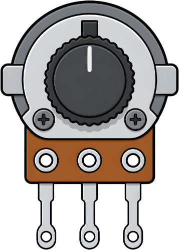
A potentiometer is a three-terminal variable resistor that allows users to adjust voltage levels in a circuit. By varying its resistance, it can control current flow and signal levels, making it a versatile component in electronics. Potentiometers are commonly used for tasks such as adjusting volume in audio devices, tuning circuits, and controlling brightness in displays.

Explore Projects Built with Potentiometer

Use Cirkit Designer to design, explore, and prototype these projects online. Some projects support real-time simulation. Click "Open Project" to start designing instantly!
Arduino 101 Analog Input Control with Trimmer Potentiometer
Image of Analog read potentiometer: A project utilizing Potentiometer in a practical application
This circuit features an Arduino 101 connected to a trimmer potentiometer. The potentiometer is used as a voltage divider, with one end connected to the Arduino's VIN for power, the wiper connected to analog input A0 for variable voltage reading, and the other end connected to GND. This setup allows the Arduino to read the position of the potentiometer's wiper as an analog value.
Cirkit Designer LogoOpen Project in Cirkit Designer
Arduino UNO Potentiometer Analog Input Project
Image of lesson 7: A project utilizing Potentiometer in a practical application
This circuit consists of an Arduino UNO microcontroller connected to a potentiometer. The potentiometer's VCC and GND pins are connected to the 5V and GND pins of the Arduino, respectively, and its output is connected to the A1 analog input pin of the Arduino, allowing the Arduino to read varying voltage levels from the potentiometer.
Cirkit Designer LogoOpen Project in Cirkit Designer
Arduino UNO R4 WiFi Analog Input with Potentiometer
Image of potentiometer: A project utilizing Potentiometer in a practical application
This circuit consists of a potentiometer connected to an Arduino UNO R4 WiFi. The potentiometer's ground and VCC are connected to the Arduino's ground and 5V pins, respectively, and its output is connected to the Arduino's analog input A0. The purpose of this circuit is likely to read the variable resistance from the potentiometer as an analog voltage, which can be used by the Arduino for various control applications.
Cirkit Designer LogoOpen Project in Cirkit Designer
Arduino UNO Analog Input with Trimmer Potentiometer
Image of Potenciometer: A project utilizing Potentiometer in a practical application
This circuit features an Arduino UNO connected to a trimmer potentiometer. The potentiometer's adjustable output is fed into the Arduino's analog input A0 for voltage measurement, enabling the microcontroller to monitor or control an analog parameter.
Cirkit Designer LogoOpen Project in Cirkit Designer

Explore Projects Built with Potentiometer

Use Cirkit Designer to design, explore, and prototype these projects online. Some projects support real-time simulation. Click "Open Project" to start designing instantly!
Image of Analog read potentiometer: A project utilizing Potentiometer in a practical application
Arduino 101 Analog Input Control with Trimmer Potentiometer
This circuit features an Arduino 101 connected to a trimmer potentiometer. The potentiometer is used as a voltage divider, with one end connected to the Arduino's VIN for power, the wiper connected to analog input A0 for variable voltage reading, and the other end connected to GND. This setup allows the Arduino to read the position of the potentiometer's wiper as an analog value.
Cirkit Designer LogoOpen Project in Cirkit Designer
Image of lesson 7: A project utilizing Potentiometer in a practical application
Arduino UNO Potentiometer Analog Input Project
This circuit consists of an Arduino UNO microcontroller connected to a potentiometer. The potentiometer's VCC and GND pins are connected to the 5V and GND pins of the Arduino, respectively, and its output is connected to the A1 analog input pin of the Arduino, allowing the Arduino to read varying voltage levels from the potentiometer.
Cirkit Designer LogoOpen Project in Cirkit Designer
Image of potentiometer: A project utilizing Potentiometer in a practical application
Arduino UNO R4 WiFi Analog Input with Potentiometer
This circuit consists of a potentiometer connected to an Arduino UNO R4 WiFi. The potentiometer's ground and VCC are connected to the Arduino's ground and 5V pins, respectively, and its output is connected to the Arduino's analog input A0. The purpose of this circuit is likely to read the variable resistance from the potentiometer as an analog voltage, which can be used by the Arduino for various control applications.
Cirkit Designer LogoOpen Project in Cirkit Designer
Image of Potenciometer: A project utilizing Potentiometer in a practical application
Arduino UNO Analog Input with Trimmer Potentiometer
This circuit features an Arduino UNO connected to a trimmer potentiometer. The potentiometer's adjustable output is fed into the Arduino's analog input A0 for voltage measurement, enabling the microcontroller to monitor or control an analog parameter.
Cirkit Designer LogoOpen Project in Cirkit Designer

Common Applications:

  • Volume control in audio systems
  • Brightness adjustment in LED circuits
  • Calibration and tuning in electronic devices
  • Position sensing in joysticks and rotary encoders

Technical Specifications

Below are the general specifications for a standard potentiometer. Note that specific values may vary depending on the model and manufacturer.

Parameter Specification
Resistance Range 1 kΩ to 1 MΩ (common values: 10 kΩ)
Power Rating 0.1 W to 1 W
Tolerance ±10% to ±20%
Operating Voltage Up to 50 V
Rotation Angle 270° (typical for rotary types)
Temperature Range -40°C to +125°C

Pin Configuration

A potentiometer typically has three pins:

Pin Description
Pin 1 Fixed end of the resistor (connect to VCC or GND)
Pin 2 Wiper (variable output voltage)
Pin 3 Fixed end of the resistor (connect to GND or VCC)

Usage Instructions

How to Use a Potentiometer in a Circuit

  1. Connect the Fixed Ends: Attach Pin 1 to the positive voltage source (VCC) and Pin 3 to ground (GND). Alternatively, you can reverse these connections depending on your circuit design.
  2. Connect the Wiper: Pin 2 (the wiper) provides the variable voltage output. Connect this pin to the input of the circuit where you need adjustable voltage.
  3. Adjust the Resistance: Rotate the potentiometer's knob or slider to change the resistance and adjust the output voltage.

Important Considerations:

  • Power Rating: Ensure the potentiometer's power rating is sufficient for your application to avoid overheating.
  • Mechanical Limits: Do not force the potentiometer beyond its rotation or sliding limits, as this can damage the component.
  • Noise: In some cases, potentiometers may introduce electrical noise. Use high-quality components for sensitive applications.

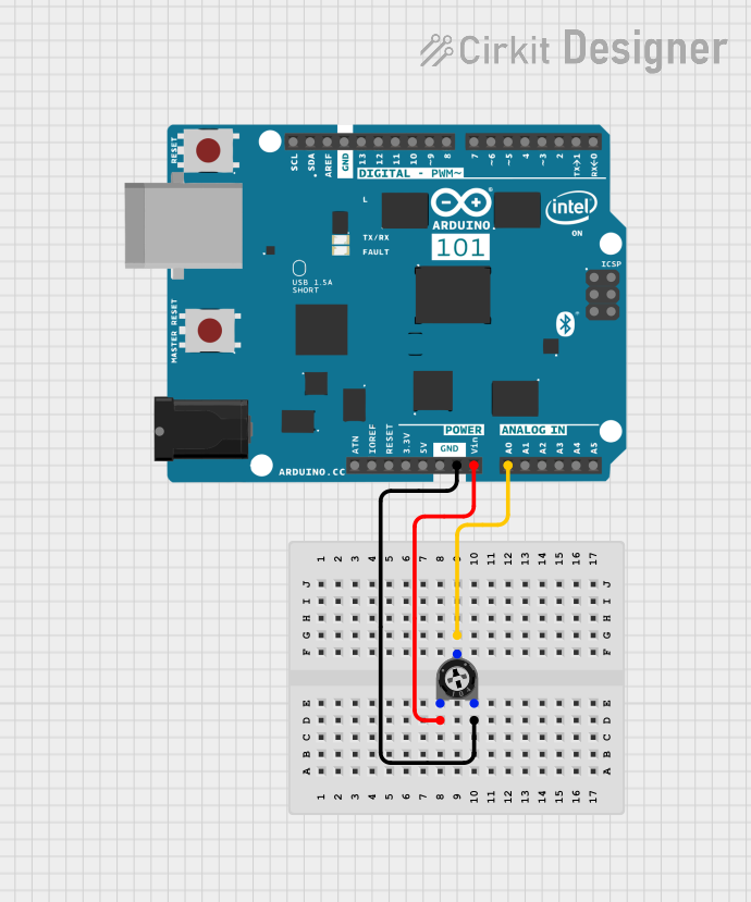
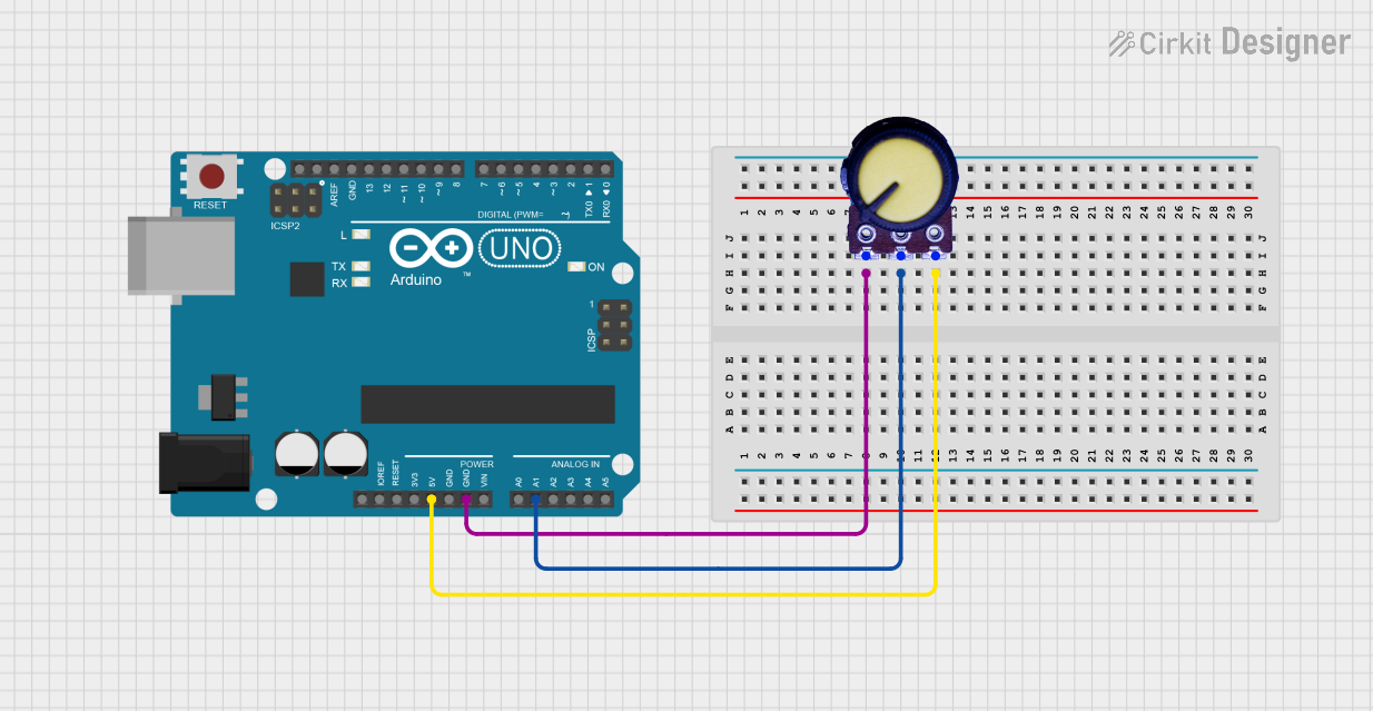
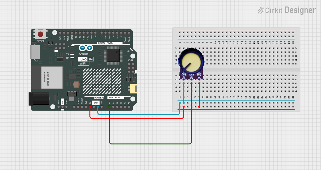
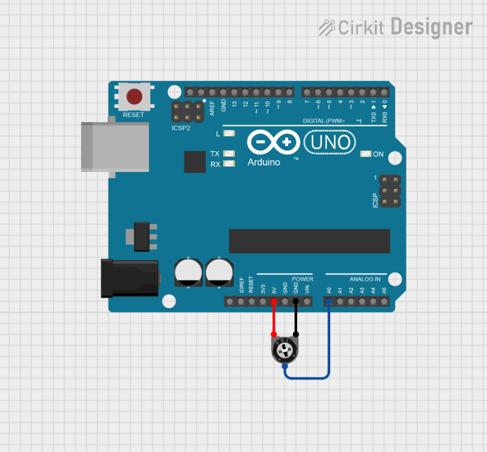
Example: Using a Potentiometer with Arduino UNO

Below is an example of how to use a 10 kΩ potentiometer to control the brightness of an LED using an Arduino UNO.

Circuit Connections:

  • Pin 1: Connect to 5V (VCC) on the Arduino.
  • Pin 3: Connect to GND on the Arduino.
  • Pin 2: Connect to analog input A0 on the Arduino.
  • LED: Connect the positive leg to digital pin 9 (via a 220 Ω resistor) and the negative leg to GND.

Arduino Code:

// Define pin connections
const int potPin = A0;  // Potentiometer wiper connected to analog pin A0
const int ledPin = 9;   // LED connected to digital pin 9 (PWM output)

void setup() {
  pinMode(ledPin, OUTPUT);  // Set LED pin as output
}

void loop() {
  int potValue = analogRead(potPin);  // Read potentiometer value (0-1023)
  
  // Map the potentiometer value to a PWM range (0-255)
  int ledBrightness = map(potValue, 0, 1023, 0, 255);
  
  analogWrite(ledPin, ledBrightness);  // Set LED brightness
}

Notes:

  • The map() function scales the potentiometer's analog input (0-1023) to the PWM range (0-255).
  • Ensure the LED's current-limiting resistor is appropriate for the LED's specifications.

Troubleshooting and FAQs

Common Issues:

  1. No Output Voltage:

    • Check the connections to ensure the potentiometer is wired correctly.
    • Verify that the potentiometer is not damaged or worn out.
  2. Inconsistent or Noisy Output:

    • Dust or wear on the potentiometer's internal track can cause noise. Clean or replace the potentiometer if necessary.
    • Use a capacitor across the wiper and ground to reduce noise in sensitive circuits.
  3. Overheating:

    • Ensure the potentiometer's power rating matches the circuit's requirements.
    • Reduce the current passing through the potentiometer if it exceeds the rated power.

FAQs:

Q: Can I use a potentiometer to directly control a motor?
A: No, a potentiometer cannot handle the high current required by most motors. Use it to control a motor driver or PWM signal instead.

Q: What is the difference between a linear and logarithmic potentiometer?
A: A linear potentiometer changes resistance proportionally to the rotation angle, while a logarithmic potentiometer changes resistance exponentially, making it suitable for audio applications.

Q: How do I know the resistance value of my potentiometer?
A: The resistance value is usually printed on the body of the potentiometer (e.g., "10k" for 10 kΩ). You can also measure it using a multimeter.

By following this documentation, you can effectively use a potentiometer in your electronic projects!