How to Use gear motor: Examples, Pinouts, and Specs
Introduction
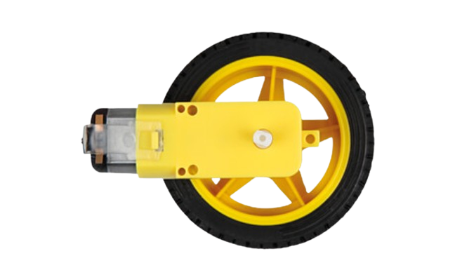
A gear motor is an electric motor integrated with a gear system to reduce speed and increase torque. This combination makes it ideal for applications requiring high torque at low speeds. Gear motors are widely used in robotics, conveyor systems, industrial machinery, and automotive applications. They are particularly valued for their ability to deliver precise motion control and power transmission.
Manufacturer: Rajesh Shah
Part ID: motor
Explore Projects Built with gear motor


Explore Projects Built with gear motor
Technical Specifications
Below are the key technical details for the gear motor:
| Parameter | Value |
|---|---|
| Operating Voltage | 6V - 12V |
| Rated Torque | 5 kg·cm - 20 kg·cm (varies by model) |
| No-Load Speed | 30 RPM - 300 RPM |
| Gear Ratio | 10:1 to 100:1 (varies by model) |
| Current Consumption | 100 mA - 1.5 A (depending on load) |
| Shaft Diameter | 6 mm |
| Motor Type | Brushed DC Motor |
| Operating Temperature | -10°C to 50°C |
| Weight | 150 g - 500 g (varies by model) |
Pin Configuration and Descriptions
The gear motor typically has two terminals for electrical connections:
| Pin | Description |
|---|---|
| + | Positive terminal for power input |
| - | Negative terminal for power input (ground) |
For bidirectional control, the motor can be connected to an H-bridge motor driver.
Usage Instructions
How to Use the Gear Motor in a Circuit
- Power Supply: Connect the gear motor to a DC power supply within the specified voltage range (6V - 12V). Ensure the power supply can provide sufficient current for the motor's operation.
- Motor Driver: Use an H-bridge motor driver (e.g., L298N or L293D) to control the motor's direction and speed. The driver allows for bidirectional rotation and PWM speed control.
- Mounting: Secure the motor using screws or brackets to prevent movement during operation. Ensure the shaft is aligned with the load to avoid stress on the motor.
- Load Connection: Attach the load to the motor shaft using a coupling or gear system. Ensure the load does not exceed the motor's rated torque.
Important Considerations and Best Practices
- Avoid Overloading: Do not exceed the motor's rated torque or current, as this may cause overheating or damage.
- Heat Dissipation: Allow proper ventilation or use a heat sink if the motor operates continuously under high load.
- Reverse Polarity: Ensure correct polarity when connecting the motor to avoid damage.
- PWM Control: Use pulse-width modulation (PWM) to control the motor's speed efficiently.
- Noise Suppression: Add capacitors (e.g., 0.1 µF) across the motor terminals to reduce electrical noise.
Example: Controlling a Gear Motor with Arduino UNO
Below is an example of how to control the gear motor using an Arduino UNO and an L298N motor driver:
// Gear Motor Control with Arduino UNO and L298N Motor Driver
// Connect the motor to the L298N motor driver outputs (OUT1 and OUT2).
// IN1 and IN2 of the L298N are connected to Arduino pins 9 and 10.

#define IN1 9  // L298N IN1 connected to Arduino pin 9
#define IN2 10 // L298N IN2 connected to Arduino pin 10
#define ENA 5  // L298N ENA (enable pin) connected to Arduino pin 5

void setup() {
  pinMode(IN1, OUTPUT); // Set IN1 as output
  pinMode(IN2, OUTPUT); // Set IN2 as output
  pinMode(ENA, OUTPUT); // Set ENA as output
}

void loop() {
  // Rotate motor clockwise
  digitalWrite(IN1, HIGH); // IN1 HIGH
  digitalWrite(IN2, LOW);  // IN2 LOW
  analogWrite(ENA, 128);   // Set speed (0-255, 128 = 50% duty cycle)
  delay(2000);             // Run for 2 seconds

  // Stop motor
  digitalWrite(IN1, LOW);  // IN1 LOW
  digitalWrite(IN2, LOW);  // IN2 LOW
  delay(1000);             // Wait for 1 second

  // Rotate motor counterclockwise
  digitalWrite(IN1, LOW);  // IN1 LOW
  digitalWrite(IN2, HIGH); // IN2 HIGH
  analogWrite(ENA, 128);   // Set speed (0-255, 128 = 50% duty cycle)
  delay(2000);             // Run for 2 seconds

  // Stop motor
  digitalWrite(IN1, LOW);  // IN1 LOW
  digitalWrite(IN2, LOW);  // IN2 LOW
  delay(1000);             // Wait for 1 second
}
Troubleshooting and FAQs
Common Issues and Solutions
Motor Does Not Rotate:
- Check the power supply voltage and current. Ensure it meets the motor's requirements.
- Verify the connections to the motor driver and Arduino.
- Ensure the motor driver enable pin (ENA) is set correctly.
Motor Overheats:
- Reduce the load on the motor shaft.
- Check for obstructions or misalignment in the load.
- Ensure the motor is operating within its rated voltage and current.
Motor Vibrates but Does Not Turn:
- Check for loose connections or poor solder joints.
- Verify the polarity of the motor connections.
Noisy Operation:
- Add capacitors across the motor terminals to suppress electrical noise.
- Ensure the motor is securely mounted to reduce mechanical vibrations.
FAQs
Can I use the gear motor with a battery?
Yes, as long as the battery voltage and current meet the motor's requirements.What is the advantage of using a gear motor?
Gear motors provide high torque at low speeds, making them ideal for applications requiring precise motion control.Can I control the speed of the gear motor?
Yes, you can use PWM (pulse-width modulation) to control the motor's speed.What happens if I reverse the polarity?
Reversing the polarity will change the motor's rotation direction. However, ensure the motor driver supports bidirectional control to avoid damage.
This concludes the documentation for the gear motor. For further assistance, refer to the manufacturer's datasheet or contact technical support.