Cirkit Designer Logo
Cirkit Designer
Your all-in-one circuit design IDE
Home / 
Component Documentation

How to Use Servo mg90s: Examples, Pinouts, and Specs

Image of Servo mg90s
Cirkit Designer LogoDesign with Servo mg90s in Cirkit Designer

Introduction

The MG90S is a small, lightweight servo motor widely used in robotics, RC vehicles, and hobby projects. It features a metal gear design, which enhances durability and precision compared to plastic gear servos. The MG90S operates within a voltage range of 4.8V to 6.0V and delivers a torque of approximately 2.2 kg/cm at 6V. Its compact size and reliable performance make it ideal for applications requiring precise control of mechanical movements, such as robotic arms, pan-tilt mechanisms, and model airplanes.

Explore Projects Built with Servo mg90s

Use Cirkit Designer to design, explore, and prototype these projects online. Some projects support real-time simulation. Click "Open Project" to start designing instantly!
GPS-Enabled Telemetry Drone with Speedybee F405 WING and Brushless Motor
Image of Pharmadrone Wiring: A project utilizing Servo mg90s in a practical application
This circuit is designed for a remote-controlled vehicle or drone, featuring a flight controller that manages a brushless motor, servomotors for actuation, telemetry for data communication, and a GPS module for positioning. It is powered by a lipo battery and includes a receiver for remote control inputs.
Cirkit Designer LogoOpen Project in Cirkit Designer
Itsy Bitsy M0 Express Controlled Multi-Servo System
Image of Crab Robot Circuit: A project utilizing Servo mg90s in a practical application
This circuit consists of an Itsy Bitsy M0 Express microcontroller connected to eight Tower Pro SG90 servos. Each servo is controlled by a different digital or analog output pin on the microcontroller. A single power supply provides +5V and GND to all servos, and the microcontroller is configured with some of its pins interconnected for potential programming or operational purposes.
Cirkit Designer LogoOpen Project in Cirkit Designer
ESP32-Controlled 32-Channel Servo Motor Driver with Dual PCA9685 Modules
Image of Esp32_RHumanoide19GL: A project utilizing Servo mg90s in a practical application
This circuit is designed to control multiple MG90S micro servo motors using two Adafruit PCA9685 PWM Servo Breakout boards, which are interfaced with an ESP32 microcontroller. The ESP32 uses I2C communication to send PWM signals to the PCA9685 boards, which then control the position of the servos. The servos are powered by a 5V battery, and the ESP32 is powered by a separate 3.3V battery, with common ground connections throughout the circuit.
Cirkit Designer LogoOpen Project in Cirkit Designer
Arduino Mega 2560-Based Smart Lock System with Servo Control and GSM Connectivity
Image of RM Circuit Diagaram: A project utilizing Servo mg90s in a practical application
This circuit is a control system utilizing an Arduino Mega 2560 to manage multiple MG90S servos, an LCD display, a DS3231 RTC module, a SIM900A GSM module, and an ESP32 for communication. It also includes a relay module to control a 12V solenoid lock, an IR sensor for input, and a Li-ion battery for power supply.
Cirkit Designer LogoOpen Project in Cirkit Designer

Explore Projects Built with Servo mg90s

Use Cirkit Designer to design, explore, and prototype these projects online. Some projects support real-time simulation. Click "Open Project" to start designing instantly!
Image of Pharmadrone Wiring: A project utilizing Servo mg90s in a practical application
GPS-Enabled Telemetry Drone with Speedybee F405 WING and Brushless Motor
This circuit is designed for a remote-controlled vehicle or drone, featuring a flight controller that manages a brushless motor, servomotors for actuation, telemetry for data communication, and a GPS module for positioning. It is powered by a lipo battery and includes a receiver for remote control inputs.
Cirkit Designer LogoOpen Project in Cirkit Designer
Image of Crab Robot Circuit: A project utilizing Servo mg90s in a practical application
Itsy Bitsy M0 Express Controlled Multi-Servo System
This circuit consists of an Itsy Bitsy M0 Express microcontroller connected to eight Tower Pro SG90 servos. Each servo is controlled by a different digital or analog output pin on the microcontroller. A single power supply provides +5V and GND to all servos, and the microcontroller is configured with some of its pins interconnected for potential programming or operational purposes.
Cirkit Designer LogoOpen Project in Cirkit Designer
Image of Esp32_RHumanoide19GL: A project utilizing Servo mg90s in a practical application
ESP32-Controlled 32-Channel Servo Motor Driver with Dual PCA9685 Modules
This circuit is designed to control multiple MG90S micro servo motors using two Adafruit PCA9685 PWM Servo Breakout boards, which are interfaced with an ESP32 microcontroller. The ESP32 uses I2C communication to send PWM signals to the PCA9685 boards, which then control the position of the servos. The servos are powered by a 5V battery, and the ESP32 is powered by a separate 3.3V battery, with common ground connections throughout the circuit.
Cirkit Designer LogoOpen Project in Cirkit Designer
Image of RM Circuit Diagaram: A project utilizing Servo mg90s in a practical application
Arduino Mega 2560-Based Smart Lock System with Servo Control and GSM Connectivity
This circuit is a control system utilizing an Arduino Mega 2560 to manage multiple MG90S servos, an LCD display, a DS3231 RTC module, a SIM900A GSM module, and an ESP32 for communication. It also includes a relay module to control a 12V solenoid lock, an IR sensor for input, and a Li-ion battery for power supply.
Cirkit Designer LogoOpen Project in Cirkit Designer

Common Applications

  • Robotic arms and grippers
  • Pan-tilt camera systems
  • RC vehicles and airplanes
  • Automated mechanisms in hobby projects
  • Educational electronics and prototyping

Technical Specifications

Key Specifications

Parameter Value
Operating Voltage 4.8V to 6.0V
Stall Torque 1.8 kg/cm (4.8V), 2.2 kg/cm (6.0V)
Operating Speed 0.1 sec/60° (6.0V), 0.12 sec/60° (4.8V)
Gear Type Metal
Weight 13.4 g
Dimensions 22.8 x 12.2 x 28.5 mm
Control Signal PWM (Pulse Width Modulation)
PWM Pulse Range 500 µs to 2500 µs
Rotation Angle 0° to 180°
Connector Type 3-pin female header (Dupont)

Pin Configuration

The MG90S servo motor has a 3-pin connector with the following pinout:

Pin Number Wire Color Function Description
1 Brown Ground (GND) Connect to the ground of the power supply or microcontroller.
2 Red Power (VCC) Connect to a 4.8V to 6.0V power source.
3 Orange Signal (PWM) Connect to the PWM output pin of a microcontroller.

Usage Instructions

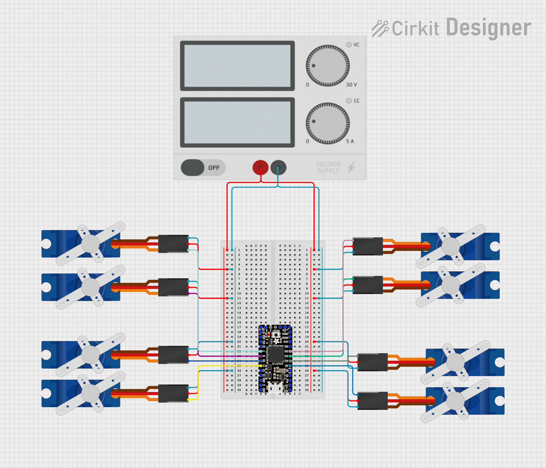
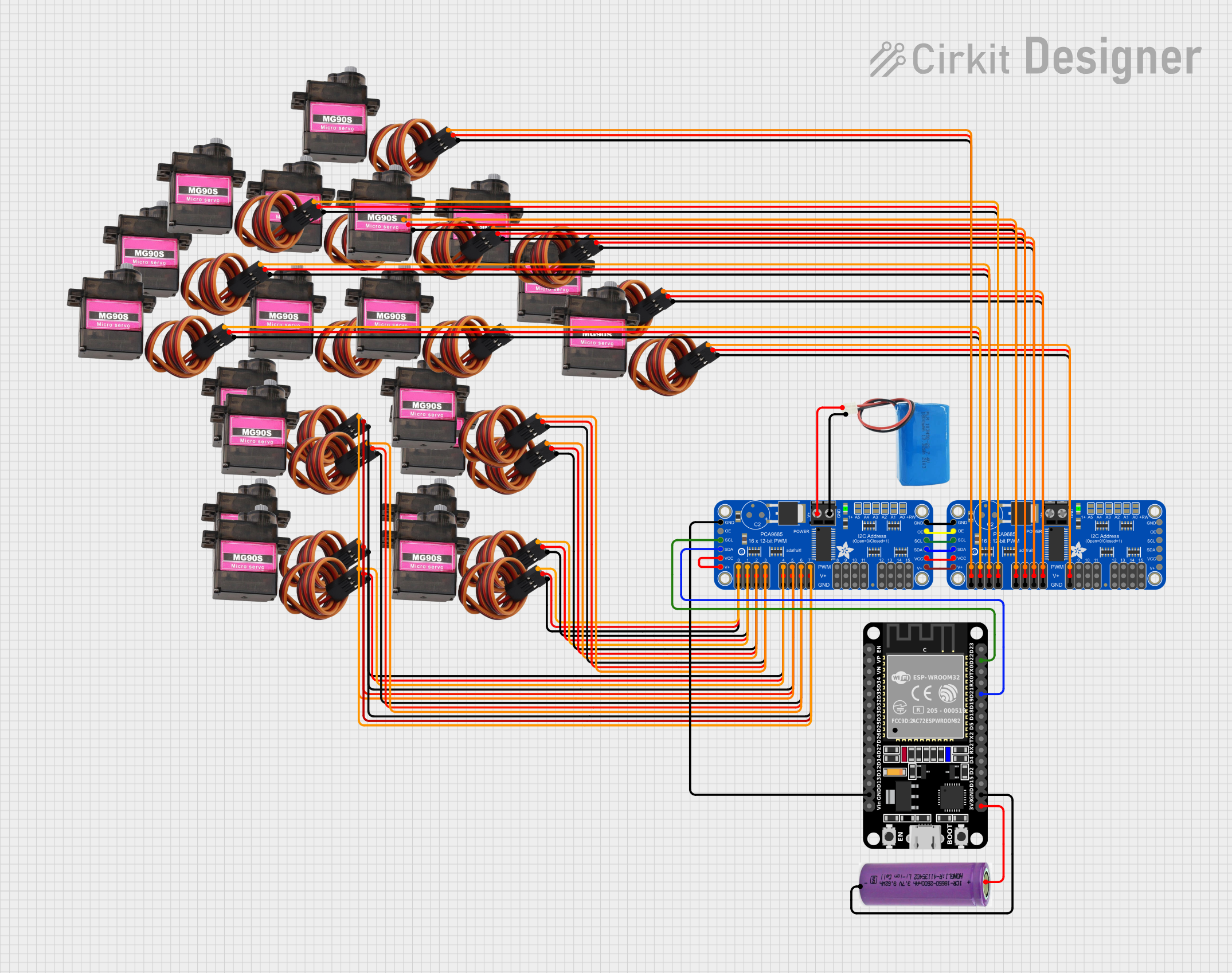
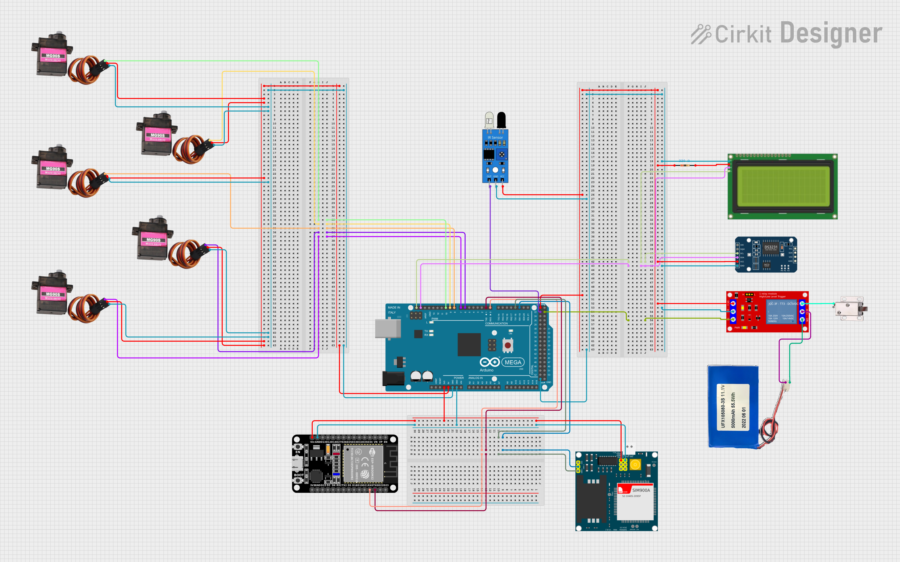
How to Use the MG90S in a Circuit

  1. Power Connection: Connect the red wire to a 4.8V to 6.0V power source and the brown wire to ground. Ensure the power supply can provide sufficient current (at least 1A) to avoid voltage drops.
  2. Signal Connection: Connect the orange wire to a PWM-capable pin on your microcontroller (e.g., Arduino).
  3. PWM Signal: Generate a PWM signal with a pulse width between 500 µs (0°) and 2500 µs (180°). A pulse width of 1500 µs corresponds to the neutral position (90°).
  4. Mounting: Use the included screws and servo horns to attach the MG90S to your project.

Important Considerations

  • Power Supply: Avoid powering the servo directly from the microcontroller's 5V pin, as it may not provide enough current. Use an external power source or a dedicated servo driver.
  • PWM Frequency: The MG90S typically operates at a PWM frequency of 50 Hz (20 ms period).
  • Overloading: Do not exceed the torque rating to prevent damage to the motor or gears.
  • Calibration: Test the servo's range of motion to ensure it does not hit physical stops, which could cause overheating or damage.

Example Code for Arduino UNO

The following example demonstrates how to control the MG90S servo using an Arduino UNO and the Servo library.

#include <Servo.h> // Include the Servo library

Servo myServo; // Create a Servo object to control the MG90S

void setup() {
  myServo.attach(9); // Attach the servo to pin 9 on the Arduino
}

void loop() {
  myServo.write(0); // Move the servo to 0 degrees
  delay(1000); // Wait for 1 second

  myServo.write(90); // Move the servo to 90 degrees
  delay(1000); // Wait for 1 second

  myServo.write(180); // Move the servo to 180 degrees
  delay(1000); // Wait for 1 second
}

Best Practices

  • Use a capacitor (e.g., 100 µF) across the power supply to stabilize voltage.
  • Avoid sudden changes in position to reduce wear on the gears.
  • Test the servo with a low load before integrating it into your project.

Troubleshooting and FAQs

Common Issues and Solutions

  1. Servo Not Moving:

    • Cause: Incorrect wiring or insufficient power supply.
    • Solution: Double-check the connections and ensure the power supply provides at least 1A.
  2. Servo Jittering:

    • Cause: Electrical noise or unstable power supply.
    • Solution: Add a capacitor across the power supply and ensure proper grounding.
  3. Limited Range of Motion:

    • Cause: Incorrect PWM signal or physical obstruction.
    • Solution: Verify the PWM pulse width and ensure the servo is not hitting any physical stops.
  4. Overheating:

    • Cause: Overloading or continuous operation at high torque.
    • Solution: Reduce the load and allow the servo to cool down periodically.

FAQs

Q: Can I power the MG90S directly from the Arduino's 5V pin?
A: It is not recommended, as the Arduino's 5V pin may not provide enough current. Use an external power source.

Q: What is the maximum rotation angle of the MG90S?
A: The MG90S can rotate approximately 180°.

Q: Can I use the MG90S with a Raspberry Pi?
A: Yes, but you will need to generate a 50 Hz PWM signal using a library like RPi.GPIO or a dedicated servo driver.

Q: How do I prevent the servo from jittering?
A: Use a stable power supply, proper grounding, and a capacitor to filter noise.