
How to Use red light 220vac: Examples, Pinouts, and Specs
 Design with red light 220vac in Cirkit Designer
Introduction
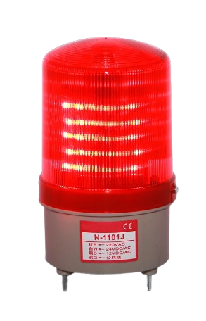
The Red Light 220VAC is a high-voltage indicator light designed to operate directly on a 220-volt AC power supply. It is commonly used in industrial and residential applications as a signal or status indicator. The component is durable, energy-efficient, and easy to integrate into electrical systems. Its bright red illumination ensures clear visibility, making it ideal for control panels, machinery, and warning systems.
Explore Projects Built with red light 220vac
 Open Project in Cirkit Designer
 Open Project in Cirkit Designer
 Open Project in Cirkit Designer
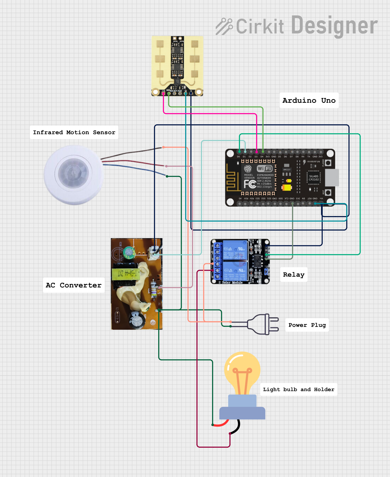 Open Project in Cirkit Designer
Explore Projects Built with red light 220vac
Open Project in Cirkit DesignerOpen Project in Cirkit DesignerOpen Project in Cirkit DesignerOpen Project in Cirkit DesignerCommon Applications
- Status indicators on control panels
- Signal lights in industrial machinery
- Warning lights in electrical systems
- Power-on indicators for appliances and devices
Technical Specifications
The following table outlines the key technical details of the Red Light 220VAC:
| Parameter | Specification |
|---|---|
| Operating Voltage | 220V AC |
| Power Consumption | Typically 0.5W to 2W |
| Light Color | Red |
| Mounting Type | Panel mount or screw-in |
| Operating Temperature | -20°C to 60°C |
| Lifespan | 10,000 to 50,000 hours (typical) |
| Housing Material | Plastic or metal (varies by model) |
| Connector Type | Screw terminals or wire leads |
Pin Configuration and Descriptions
The Red Light 220VAC typically has two connection points for AC power input. The table below describes the connections:
| Pin/Lead Name | Description |
|---|---|
| AC Live (L) | Connects to the live (hot) wire of the 220V AC supply. |
| AC Neutral (N) | Connects to the neutral wire of the 220V AC supply. |
Note: Ensure proper polarity when connecting the light to avoid incorrect operation or damage.
Usage Instructions
How to Use the Component in a Circuit
- Safety First: Before handling the Red Light 220VAC, ensure the power supply is turned off to avoid electric shock.
- Mounting: Securely mount the light in the desired location, such as a control panel or enclosure. Use the appropriate mounting hardware (e.g., screws or clips) as specified by the manufacturer.
- Wiring:
- Connect the AC Live (L) terminal of the light to the live wire of the 220V AC power supply.
- Connect the AC Neutral (N) terminal to the neutral wire of the power supply.
- Use insulated connectors or terminal blocks to ensure safe and secure connections.
- Power On: Once the wiring is complete, turn on the power supply. The red light should illuminate, indicating proper operation.
Important Considerations and Best Practices
- Voltage Compatibility: Ensure the power supply voltage matches the rated 220V AC of the light. Using a higher or lower voltage may damage the component or result in malfunction.
- Insulation: Use proper insulation for all connections to prevent short circuits or electric shock.
- Environment: Avoid exposing the light to excessive moisture, dust, or extreme temperatures unless it is specifically rated for such conditions.
- Testing: After installation, test the light to confirm it operates as expected before integrating it into a larger system.
Example Circuit
Below is a simple wiring diagram for connecting the Red Light 220VAC to a power supply:
220V AC Supply
   +-------------------+
   |                   |
   |                   |
   L (Live) --------> AC Live (L)
   N (Neutral) ------> AC Neutral (N)
   |                   |
   |                   |
   +-------------------+
Note: This component is not typically used with microcontrollers like Arduino due to its high operating voltage.
Troubleshooting and FAQs
Common Issues and Solutions
| Issue | Possible Cause | Solution |
|---|---|---|
| Light does not turn on | No power supply or loose connections | Check the power supply and wiring. |
| Flickering light | Unstable AC voltage or poor connection | Ensure stable voltage and secure connections. |
| Light burns out prematurely | Overvoltage or poor-quality component | Verify voltage and use a reliable product. |
| Light is dim | Insufficient voltage or aging component | Check the voltage and replace if necessary. |
FAQs
Q: Can I use this light with a DC power supply?
A: No, the Red Light 220VAC is designed specifically for AC power. Using a DC supply may damage the component.
Q: Is this light waterproof?
A: It depends on the specific model. Check the manufacturer's specifications for IP ratings if water resistance is required.
Q: Can I connect multiple lights in parallel?
A: Yes, multiple lights can be connected in parallel to the same 220V AC supply, provided the supply can handle the total power consumption.
Q: What should I do if the light stops working?
A: First, check the power supply and connections. If the issue persists, replace the light as it may have reached the end of its lifespan.
By following this documentation, you can safely and effectively use the Red Light 220VAC in your electrical projects.