Cirkit Designer Logo
Cirkit Designer
Your all-in-one circuit design IDE
Home / 
Component Documentation

How to Use SW420: Examples, Pinouts, and Specs

Image of SW420
Cirkit Designer LogoDesign with SW420 in Cirkit Designer

Introduction

The SW420 is a tilt switch designed to detect changes in orientation or position. It operates by closing or opening its internal contacts when tilted beyond a specific angle. This component is widely used in applications such as motion detection, anti-theft systems, orientation sensing, and robotics. Its simplicity and reliability make it a popular choice for both hobbyists and professionals.

The SW420 is manufactured by ARDUINO, with the part ID "UNO," and is compatible with a variety of microcontrollers, including the Arduino UNO.

Explore Projects Built with SW420

Use Cirkit Designer to design, explore, and prototype these projects online. Some projects support real-time simulation. Click "Open Project" to start designing instantly!
STM32F103C8T6 and ESP8266-Based Real-Time Crop Health Monitoring System with Wi-Fi Connectivity
Image of crop: A project utilizing SW420 in a practical application
This circuit is a real-time crop health monitoring system that uses an STM32F103C8T6 microcontroller to read data from an NPK soil sensor, a soil moisture sensor, and a humidity and temperature sensor. The collected data is then transmitted wirelessly via an ESP8266 module to a dashboard or mobile app for farmers to monitor crop health.
Cirkit Designer LogoOpen Project in Cirkit Designer
ESP32-Based GPS Tracker with SD Card Logging and Barometric Sensor
Image of gps projekt circuit: A project utilizing SW420 in a practical application
This circuit features an ESP32 Wroom Dev Kit as the main microcontroller, interfaced with an MPL3115A2 sensor for pressure and temperature readings, and a Neo 6M GPS module for location tracking. The ESP32 is also connected to an SD card reader for data logging purposes. A voltage regulator is used to step down the USB power supply to 3.3V, which powers the ESP32, the sensor, and the SD card reader.
Cirkit Designer LogoOpen Project in Cirkit Designer
Battery-Powered Raspberry Pi Pico GPS Tracker with Sensor Integration
Image of Copy of CanSet v1: A project utilizing SW420 in a practical application
This circuit is a data acquisition and communication system powered by a LiPoly battery and managed by a Raspberry Pi Pico. It includes sensors (BMP280, MPU9250) for environmental data, a GPS module for location tracking, an SD card for data storage, and a WLR089-CanSAT for wireless communication. The TP4056 module handles battery charging, and a toggle switch controls power distribution.
Cirkit Designer LogoOpen Project in Cirkit Designer
ESP32-Based Smart Environmental Monitoring System with Battery Power
Image of BeeHive: A project utilizing SW420 in a practical application
This circuit is a multi-sensor monitoring system powered by an ESP32 microcontroller. It includes sensors for gas (MQ135), vibration (SW-420), weight (HX711 with a load cell), and temperature/humidity (DHT22), along with a buzzer for alerts. The system is powered by a 18650 Li-ion battery managed by a TP4056 charging module.
Cirkit Designer LogoOpen Project in Cirkit Designer

Explore Projects Built with SW420

Use Cirkit Designer to design, explore, and prototype these projects online. Some projects support real-time simulation. Click "Open Project" to start designing instantly!
Image of crop: A project utilizing SW420 in a practical application
STM32F103C8T6 and ESP8266-Based Real-Time Crop Health Monitoring System with Wi-Fi Connectivity
This circuit is a real-time crop health monitoring system that uses an STM32F103C8T6 microcontroller to read data from an NPK soil sensor, a soil moisture sensor, and a humidity and temperature sensor. The collected data is then transmitted wirelessly via an ESP8266 module to a dashboard or mobile app for farmers to monitor crop health.
Cirkit Designer LogoOpen Project in Cirkit Designer
Image of gps projekt circuit: A project utilizing SW420 in a practical application
ESP32-Based GPS Tracker with SD Card Logging and Barometric Sensor
This circuit features an ESP32 Wroom Dev Kit as the main microcontroller, interfaced with an MPL3115A2 sensor for pressure and temperature readings, and a Neo 6M GPS module for location tracking. The ESP32 is also connected to an SD card reader for data logging purposes. A voltage regulator is used to step down the USB power supply to 3.3V, which powers the ESP32, the sensor, and the SD card reader.
Cirkit Designer LogoOpen Project in Cirkit Designer
Image of Copy of CanSet v1: A project utilizing SW420 in a practical application
Battery-Powered Raspberry Pi Pico GPS Tracker with Sensor Integration
This circuit is a data acquisition and communication system powered by a LiPoly battery and managed by a Raspberry Pi Pico. It includes sensors (BMP280, MPU9250) for environmental data, a GPS module for location tracking, an SD card for data storage, and a WLR089-CanSAT for wireless communication. The TP4056 module handles battery charging, and a toggle switch controls power distribution.
Cirkit Designer LogoOpen Project in Cirkit Designer
Image of BeeHive: A project utilizing SW420 in a practical application
ESP32-Based Smart Environmental Monitoring System with Battery Power
This circuit is a multi-sensor monitoring system powered by an ESP32 microcontroller. It includes sensors for gas (MQ135), vibration (SW-420), weight (HX711 with a load cell), and temperature/humidity (DHT22), along with a buzzer for alerts. The system is powered by a 18650 Li-ion battery managed by a TP4056 charging module.
Cirkit Designer LogoOpen Project in Cirkit Designer

Technical Specifications

The SW420 tilt switch is a passive component with the following key specifications:

Parameter Value
Operating Voltage 3.3V to 5V
Operating Current ≤ 20mA
Output Type Digital (High/Low)
Tilt Angle Threshold Typically 15° to 45°
Dimensions 14mm x 5mm x 5mm (approx.)
Operating Temperature -40°C to +85°C

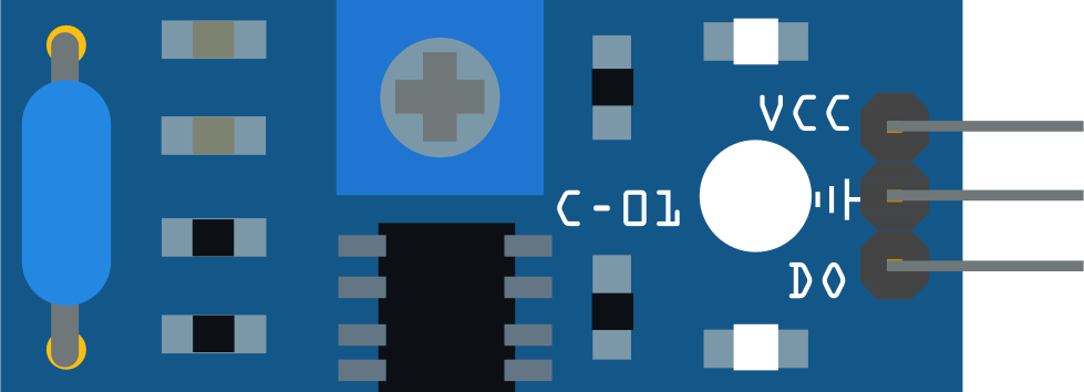
Pin Configuration and Descriptions

The SW420 module typically comes with three pins:

Pin Name Description
VCC Power supply pin (3.3V to 5V)
GND Ground connection
DO Digital output pin (HIGH when stable, LOW when tilted)

Usage Instructions

The SW420 tilt switch is straightforward to use in a circuit. Below are the steps and best practices for integrating it into your project:

  1. Wiring the Component:

    • Connect the VCC pin to a 3.3V or 5V power source.
    • Connect the GND pin to the ground of your circuit.
    • Connect the DO (Digital Output) pin to a digital input pin on your microcontroller (e.g., Arduino UNO).
  2. Circuit Example:

    • Use a pull-up resistor (typically 10kΩ) on the DO pin to ensure stable readings.
    • Optionally, add a decoupling capacitor (e.g., 0.1µF) between VCC and GND to reduce noise.
  3. Arduino UNO Example Code: Below is an example code snippet to interface the SW420 with an Arduino UNO:

    // SW420 Tilt Switch Example Code
    // Connect SW420 DO pin to Arduino digital pin 2
    const int tiltPin = 2;  // Digital pin connected to SW420 DO pin
    const int ledPin = 13;  // Built-in LED pin for status indication
    
    void setup() {
      pinMode(tiltPin, INPUT);  // Set tiltPin as input
      pinMode(ledPin, OUTPUT); // Set ledPin as output
      Serial.begin(9600);      // Initialize serial communication
    }
    
    void loop() {
      int tiltState = digitalRead(tiltPin); // Read the state of the tilt switch
    
      if (tiltState == LOW) {
        // If the switch is tilted, turn on the LED
        digitalWrite(ledPin, HIGH);
        Serial.println("Tilt detected!");
      } else {
        // If the switch is stable, turn off the LED
        digitalWrite(ledPin, LOW);
        Serial.println("No tilt detected.");
      }
    
      delay(100); // Small delay for stability
    }
    
  4. Important Considerations:

    • Ensure the SW420 is mounted securely in your project to avoid false triggers due to vibrations.
    • Avoid exposing the component to excessive moisture or extreme temperatures beyond its operating range.
    • Use debounce logic in your code if the tilt switch is prone to rapid state changes.

Troubleshooting and FAQs

Common Issues and Solutions

  1. Issue: The SW420 is not detecting tilt.

    • Solution: Verify the wiring connections, especially the VCC and GND pins. Ensure the power supply voltage is within the specified range (3.3V to 5V).
  2. Issue: The output is unstable or noisy.

    • Solution: Add a pull-up resistor (10kΩ) to the DO pin and a decoupling capacitor (0.1µF) between VCC and GND to stabilize the signal.
  3. Issue: The Arduino does not respond to tilt events.

    • Solution: Check the code to ensure the correct digital pin is being read. Use the Serial.println() function to debug the tilt state.
  4. Issue: False triggers occur due to vibrations.

    • Solution: Mount the SW420 securely and consider adding software debounce logic to filter out rapid state changes.

FAQs

  • Q: Can the SW420 detect small tilts?
    A: The SW420 is designed to detect tilts within a threshold angle of 15° to 45°. For smaller tilt detection, consider using a more sensitive sensor like an accelerometer.

  • Q: Is the SW420 suitable for outdoor use?
    A: The SW420 is not waterproof or weatherproof. If used outdoors, it must be enclosed in a protective casing.

  • Q: Can I use the SW420 with a 3.3V microcontroller?
    A: Yes, the SW420 operates within a voltage range of 3.3V to 5V, making it compatible with 3.3V microcontrollers.

By following this documentation, you can effectively integrate the SW420 tilt switch into your projects and troubleshoot any issues that arise.