How to Use 30A Relay Board: Examples, Pinouts, and Specs
Introduction
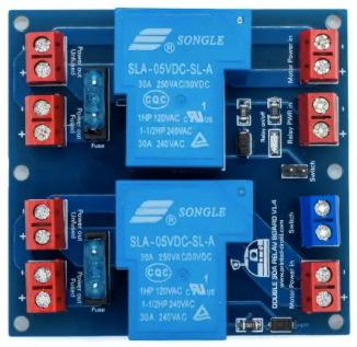
The 30A Relay Board (Manufacturer Part ID: Droid Motor 30A Relay Board) by Printed-Droid.com is a high-power relay module designed to control devices with a maximum current rating of 30A. This board is ideal for applications requiring the automation of electrical circuits, such as motor control, home automation, industrial equipment, and lighting systems. It allows low-voltage control signals to safely switch high-power loads, making it a versatile and essential component for many electronic projects.
Explore Projects Built with 30A Relay Board
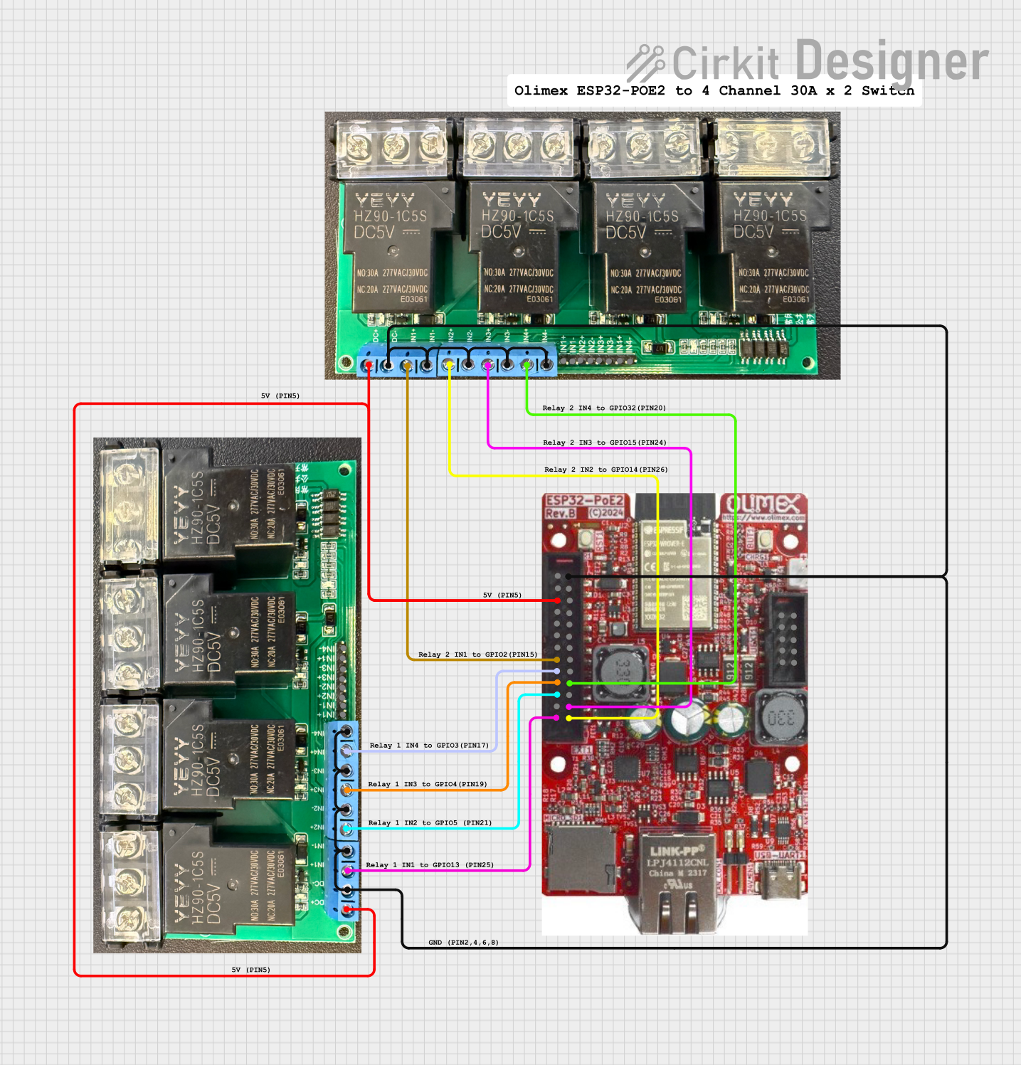


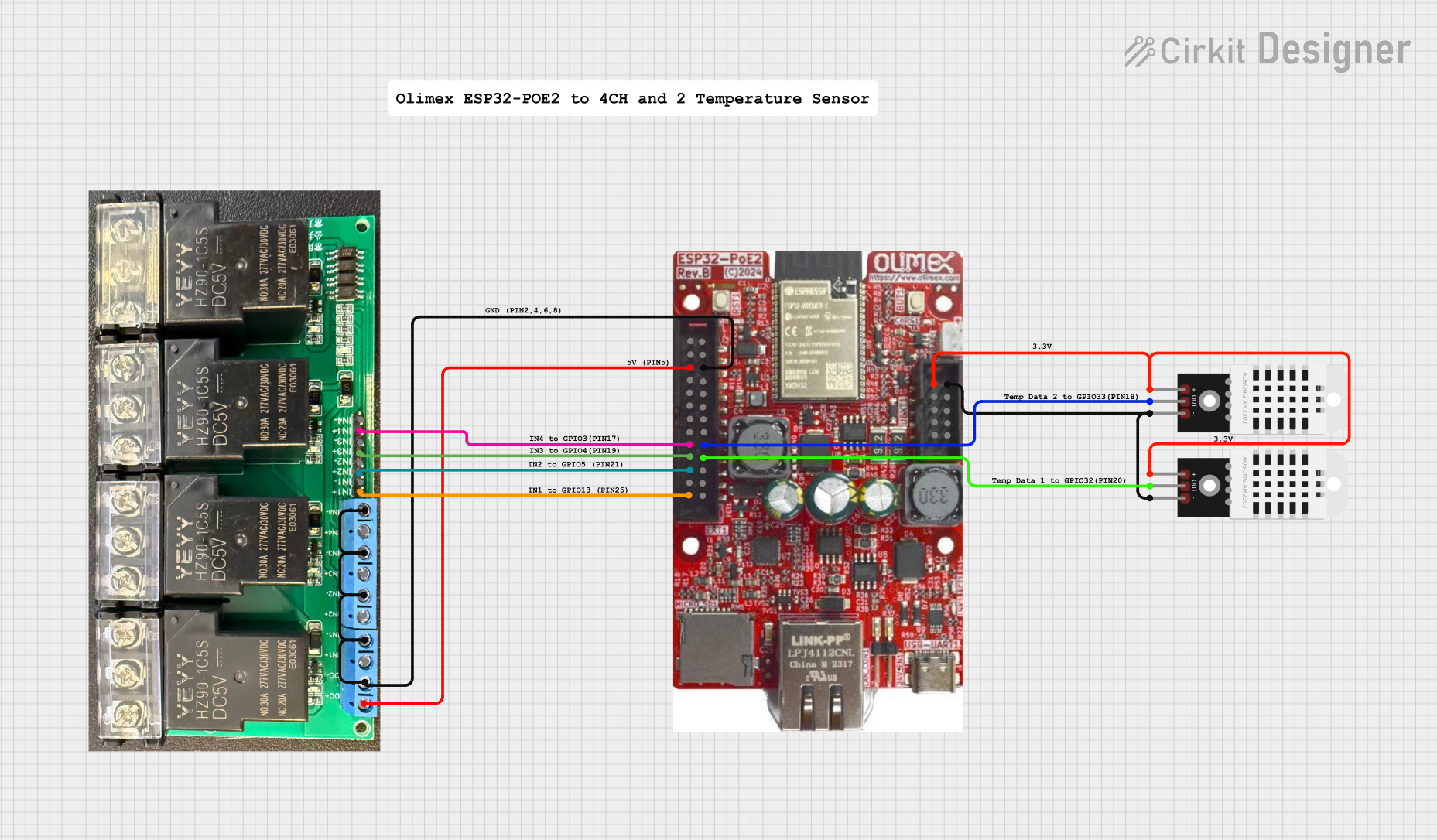
Explore Projects Built with 30A Relay Board
Common Applications
- Home automation systems (e.g., controlling lights, fans, or appliances)
- Motor control in robotics and industrial machinery
- High-power LED lighting systems
- HVAC systems
- Smart energy management systems
Technical Specifications
The following table outlines the key technical details of the 30A Relay Board:
| Parameter | Specification |
|---|---|
| Operating Voltage | 5V DC or 12V DC (model-dependent) |
| Maximum Load Current | 30A per relay |
| Maximum Load Voltage | 250V AC / 30V DC |
| Number of Relays | 1 to 4 (depending on model) |
| Control Signal Voltage | 3.3V to 5V DC |
| Relay Type | SPDT (Single Pole Double Throw) |
| Isolation | Optocoupler isolation for signal safety |
| Dimensions | Varies by model (e.g., 50mm x 70mm for 1-relay version) |
| Mounting | Screw holes for secure installation |
Pin Configuration and Descriptions
The 30A Relay Board typically includes the following pins for each relay:
| Pin Name | Description |
|---|---|
| VCC | Power supply input for the relay board (5V or 12V, depending on the model). |
| GND | Ground connection. |
| INx | Control signal input for relay x (e.g., IN1 for Relay 1, IN2 for Relay 2, etc.). |
| COM | Common terminal of the relay. |
| NO | Normally Open terminal of the relay. When activated, this connects to COM. |
| NC | Normally Closed terminal of the relay. When deactivated, this connects to COM. |
Note: The number of
INx,COM,NO, andNCpins depends on the number of relays on the board.
Usage Instructions
How to Use the 30A Relay Board in a Circuit
- Power the Relay Board: Connect the
VCCpin to a 5V or 12V DC power source (depending on the model) and theGNDpin to the ground of your circuit. - Connect the Control Signal: Use a microcontroller (e.g., Arduino UNO) or other control device to send a signal to the
INxpin(s). A HIGH signal (3.3V or 5V) typically activates the relay. - Connect the Load:
- Connect the device you want to control to the
COMandNOorNCterminals of the relay. - Use
NOif you want the device to turn on when the relay is activated. - Use
NCif you want the device to turn off when the relay is activated.
- Connect the device you want to control to the
- Test the Circuit: Ensure all connections are secure and test the circuit by toggling the control signal.
Important Considerations and Best Practices
- Power Supply: Ensure the relay board's power supply matches its operating voltage (5V or 12V).
- Load Ratings: Do not exceed the maximum current (30A) or voltage (250V AC / 30V DC) ratings of the relay.
- Isolation: The board includes optocoupler isolation for safety, but always exercise caution when working with high-power circuits.
- Heat Dissipation: For continuous high-current loads, ensure proper ventilation or heat dissipation to prevent overheating.
- Inductive Loads: When controlling inductive loads (e.g., motors), use a flyback diode across the load to protect the relay from voltage spikes.
Example: Connecting to an Arduino UNO
Below is an example of how to control a single relay on the 30A Relay Board using an Arduino UNO:
Circuit Connections
- Connect the
VCCpin of the relay board to the Arduino's 5V pin. - Connect the
GNDpin of the relay board to the Arduino's GND pin. - Connect the
IN1pin of the relay board to Arduino digital pin 7. - Connect the load (e.g., a light bulb) to the
COMandNOterminals of the relay.
Arduino Code
// Define the relay control pin
const int relayPin = 7;

void setup() {
  // Set the relay pin as an output
  pinMode(relayPin, OUTPUT);

  // Initialize the relay as OFF
  digitalWrite(relayPin, LOW);
}

void loop() {
  // Turn the relay ON
  digitalWrite(relayPin, HIGH);
  delay(5000); // Keep the relay ON for 5 seconds

  // Turn the relay OFF
  digitalWrite(relayPin, LOW);
  delay(5000); // Keep the relay OFF for 5 seconds
}
Note: Adjust the
relayPinvariable if you connect the relay to a different Arduino pin.
Troubleshooting and FAQs
Common Issues and Solutions
Relay Not Activating
- Cause: Insufficient control signal voltage.
- Solution: Ensure the control signal voltage is within the specified range (3.3V to 5V).
Load Not Turning On/Off
- Cause: Incorrect wiring of the load to the relay terminals.
- Solution: Verify the load is connected to the correct terminals (
COM,NO, orNC).
Overheating
- Cause: Continuous high-current operation without proper ventilation.
- Solution: Add a heatsink or ensure adequate airflow around the relay board.
Relay Clicking Noise
- Cause: Rapid toggling of the control signal.
- Solution: Add a delay in the control signal to prevent rapid switching.
FAQs
Q: Can I use the relay board with a 3.3V microcontroller?
A: Yes, the relay board supports control signals as low as 3.3V, making it compatible with 3.3V microcontrollers like the ESP32.Q: Can I control multiple relays simultaneously?
A: Yes, you can control multiple relays by connecting eachINxpin to a separate microcontroller pin.Q: Is the relay board safe for high-power applications?
A: Yes, the board is designed for high-power applications up to 30A, but always follow safety guidelines and ensure proper wiring.Q: Can I use the relay board to control DC motors?
A: Yes, the relay board can control DC motors, but use a flyback diode to protect the relay from voltage spikes caused by the motor.
By following this documentation, you can effectively integrate the 30A Relay Board into your projects and ensure safe and reliable operation.