How to Use GB/T AC: Examples, Pinouts, and Specs

Introduction
GB/T AC refers to a Chinese national standard for alternating current (AC) electrical systems. It defines the specifications for safety, performance, and interoperability of AC equipment, ensuring compatibility and reliability in various applications. This standard is widely used in industrial, commercial, and residential electrical systems in China.
Explore Projects Built with GB/T AC

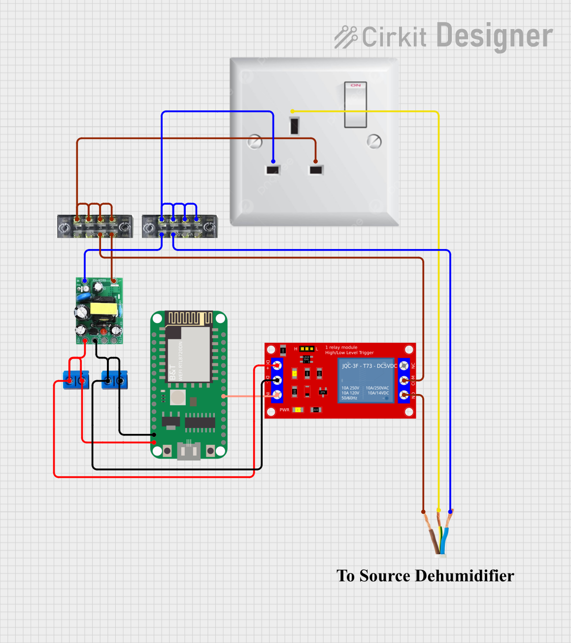

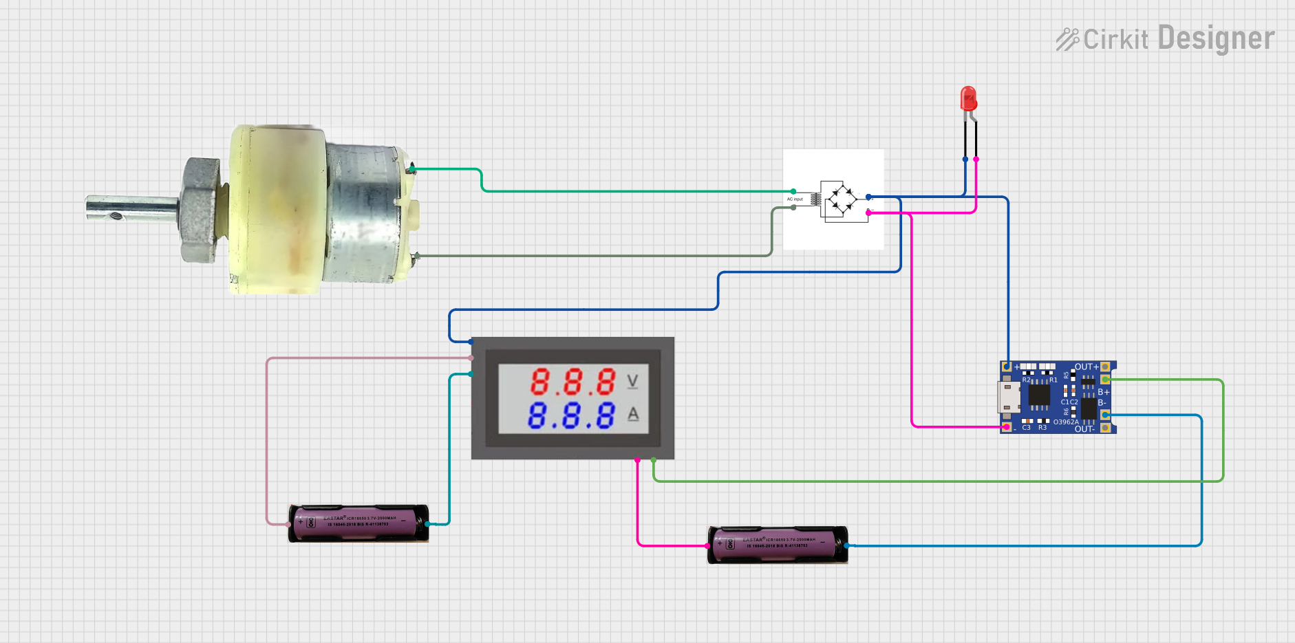
Explore Projects Built with GB/T AC
Common Applications and Use Cases
- Power distribution systems in residential, commercial, and industrial settings
- Electrical equipment design and manufacturing
- Testing and certification of AC devices for compliance with safety standards
- Integration of AC systems in renewable energy solutions, such as solar inverters and wind turbines
Technical Specifications
The GB/T AC standard outlines the following key technical parameters for AC systems:
General Specifications
| Parameter | Value/Range | Description |
|---|---|---|
| Voltage Range | 220V (single-phase) / 380V (three-phase) | Standard operating voltages in China |
| Frequency | 50 Hz | Standard AC frequency in China |
| Power Factor | ≥ 0.8 | Minimum acceptable power factor |
| Total Harmonic Distortion (THD) | ≤ 5% | Maximum allowable distortion in the AC waveform |
| Insulation Resistance | ≥ 1 MΩ | Minimum insulation resistance for safety |
Pin Configuration and Descriptions
For devices adhering to the GB/T AC standard, the pin configuration typically follows the standard AC power plug and socket design. Below is a general description of the pin layout:
| Pin Name | Description | Notes |
|---|---|---|
| Line (L) | Live wire carrying the AC voltage | Connected to the power source |
| Neutral (N) | Return path for the current | Completes the circuit |
| Earth (E) | Ground connection for safety | Prevents electric shock in case of faults |
Usage Instructions
How to Use the Component in a Circuit
- Verify Voltage and Frequency Compatibility: Ensure that the device or system is designed to operate at 220V/50Hz (single-phase) or 380V/50Hz (three-phase) as specified by the GB/T AC standard.
- Connect the Wires Properly:
- Connect the Line (L) wire to the live terminal of the device.
- Connect the Neutral (N) wire to the neutral terminal.
- Connect the Earth (E) wire to the ground terminal for safety.
- Use Proper Circuit Protection:
- Install circuit breakers or fuses rated for the current and voltage of the system.
- Use surge protectors to safeguard against voltage spikes.
- Test the System:
- Measure the voltage and frequency using a multimeter to confirm compliance with the GB/T AC standard.
- Check for proper grounding to ensure safety.
Important Considerations and Best Practices
- Safety First: Always disconnect the power supply before working on the circuit to avoid electric shock.
- Compliance: Use components and devices certified to meet the GB/T AC standard to ensure compatibility and safety.
- Grounding: Proper grounding is essential to prevent electrical hazards and ensure system stability.
- Load Balancing: For three-phase systems, distribute the load evenly across all phases to avoid overloading.
Example: Connecting a GB/T AC-Compliant Device to an Arduino UNO
While the Arduino UNO operates on DC power, you can use a relay module to control an AC device compliant with the GB/T AC standard. Below is an example code snippet for controlling an AC light using a relay module:
// Example: Controlling an AC light with Arduino and a relay module
// Ensure the relay module is rated for 220V/50Hz AC operation

const int relayPin = 7; // Pin connected to the relay module

void setup() {
  pinMode(relayPin, OUTPUT); // Set relay pin as output
  digitalWrite(relayPin, LOW); // Initialize relay to OFF state
}

void loop() {
  digitalWrite(relayPin, HIGH); // Turn ON the AC light
  delay(5000); // Keep the light ON for 5 seconds
  digitalWrite(relayPin, LOW); // Turn OFF the AC light
  delay(5000); // Keep the light OFF for 5 seconds
}
Note: Ensure proper isolation between the AC and DC sides of the circuit to prevent damage to the Arduino and ensure user safety.
Troubleshooting and FAQs
Common Issues Users Might Face
Voltage Mismatch:
- Issue: The device does not operate or malfunctions.
- Solution: Verify that the input voltage matches the GB/T AC standard (220V/50Hz or 380V/50Hz).
Improper Grounding:
- Issue: Electric shocks or unstable operation.
- Solution: Check the ground connection and ensure it is properly installed.
Overloading:
- Issue: Circuit breakers trip frequently.
- Solution: Reduce the load on the circuit or upgrade the breaker to a higher current rating, if appropriate.
Harmonic Distortion:
- Issue: Devices experience interference or reduced efficiency.
- Solution: Use power conditioning equipment, such as filters, to reduce harmonic distortion.
Solutions and Tips for Troubleshooting
- Use a multimeter to measure voltage, current, and resistance for diagnosing issues.
- Inspect all connections to ensure they are secure and free from corrosion.
- If using a relay module, verify that it is rated for the AC voltage and current of the load.
- Consult the device's user manual for specific troubleshooting steps related to GB/T AC compliance.
By following this documentation, users can safely and effectively work with GB/T AC-compliant systems and devices.