How to Use IR2110: Examples, Pinouts, and Specs
Introduction
The IR2110, manufactured by Infineon Technologies AG (Part ID: INFINEON), is a high-voltage, high-speed power MOSFET and IGBT driver. It features independent high-side and low-side output channels, making it ideal for driving the gates of power transistors in half-bridge and full-bridge configurations. The IR2110 provides level shifting and isolation, ensuring efficient and reliable switching in power electronics applications.
Explore Projects Built with IR2110

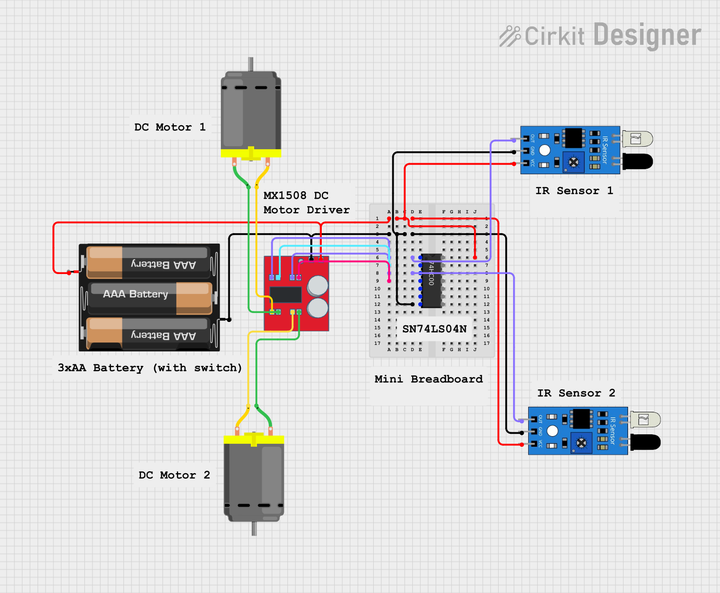


Explore Projects Built with IR2110
Common Applications
- DC-DC converters
- Motor control systems
- Inverters for renewable energy systems (e.g., solar inverters)
- Uninterruptible Power Supplies (UPS)
- High-frequency switching power supplies
Technical Specifications
Key Technical Details
| Parameter | Value |
|---|---|
| Supply Voltage (Vcc) | 10V to 20V |
| High-Side Floating Supply Voltage (Vb) | Up to 600V |
| Output Current (Peak) | 2A (source), 2A (sink) |
| Gate Drive Voltage | 10V to 20V |
| Propagation Delay (typical) | 120 ns |
| Operating Temperature Range | -40°C to +125°C |
| Package Options | DIP-14, SOIC-14 |
Pin Configuration and Descriptions
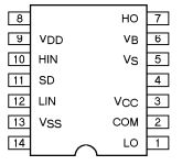
The IR2110 is available in a 14-pin package. Below is the pinout and description:
| Pin No. | Pin Name | Description |
|---|---|---|
| 1 | Vcc | Logic supply voltage (10V to 20V). |
| 2 | HIN | Logic input for high-side gate driver. Active high. |
| 3 | LIN | Logic input for low-side gate driver. Active high. |
| 4 | COM | Logic ground. |
| 5 | VSS | Low-side return. |
| 6 | LO | Low-side gate drive output. |
| 7 | VS | High-side floating supply return. |
| 8 | HO | High-side gate drive output. |
| 9 | VB | High-side floating supply voltage. |
| 10-14 | NC | Not connected (varies by package). |
Usage Instructions
How to Use the IR2110 in a Circuit
Power Supply Configuration:
- Connect the Vcc pin to a stable 10V-20V supply.
- Use a bootstrap capacitor between VB and VS to provide the high-side floating supply voltage.
Input Signals:
- Provide logic-level signals (e.g., from a microcontroller) to the HIN and LIN pins to control the high-side and low-side drivers, respectively.
- Ensure proper dead-time between HIN and LIN signals to avoid shoot-through.
Gate Drive Outputs:
- Connect the HO pin to the gate of the high-side MOSFET/IGBT and the LO pin to the gate of the low-side MOSFET/IGBT.
- Use appropriate gate resistors to limit inrush current and control switching speed.
Bootstrap Capacitor:
- Select a bootstrap capacitor (typically 0.1 µF to 1 µF) based on the gate charge of the high-side MOSFET/IGBT.
Grounding:
- Connect the COM pin to the logic ground and the VSS pin to the low-side return.
Important Considerations and Best Practices
- Dead-Time Management: Ensure sufficient dead-time between high-side and low-side switching to prevent shoot-through.
- Bootstrap Capacitor Sizing: Choose a capacitor with low ESR and sufficient capacitance to maintain the high-side supply voltage during switching.
- Thermal Management: Ensure proper heat dissipation, especially in high-frequency or high-current applications.
- Input Signal Integrity: Use clean, noise-free logic signals to drive the HIN and LIN pins.
Example: Using IR2110 with Arduino UNO
Below is an example of how to control the IR2110 using an Arduino UNO to drive a half-bridge circuit:
// Example: Controlling IR2110 with Arduino UNO
// This code generates complementary PWM signals with dead-time for a half-bridge circuit.

const int HIN_PIN = 9; // High-side input connected to Arduino pin 9
const int LIN_PIN = 10; // Low-side input connected to Arduino pin 10

void setup() {
  pinMode(HIN_PIN, OUTPUT); // Set HIN pin as output
  pinMode(LIN_PIN, OUTPUT); // Set LIN pin as output
}

void loop() {
  digitalWrite(HIN_PIN, HIGH); // Turn on high-side MOSFET
  digitalWrite(LIN_PIN, LOW);  // Ensure low-side MOSFET is off
  delayMicroseconds(10);       // Dead-time (adjust as needed)

  digitalWrite(HIN_PIN, LOW);  // Turn off high-side MOSFET
  digitalWrite(LIN_PIN, HIGH); // Turn on low-side MOSFET
  delayMicroseconds(10);       // Dead-time (adjust as needed)
}
Troubleshooting and FAQs
Common Issues and Solutions
High-Side Driver Not Working:
- Check the bootstrap capacitor connection and ensure it is properly sized.
- Verify that the VB pin voltage is sufficiently higher than the VS pin voltage.
Excessive Heat:
- Ensure proper dead-time between high-side and low-side switching.
- Use appropriate gate resistors to limit switching losses.
No Output Signal:
- Verify the input signals (HIN and LIN) are within the logic voltage range.
- Check the Vcc supply voltage and ensure it is stable.
Shoot-Through in MOSFETs:
- Increase the dead-time between HIN and LIN signals.
- Verify the gate drive signals with an oscilloscope.
FAQs
Q1: Can the IR2110 drive both N-channel and P-channel MOSFETs?
A1: The IR2110 is designed to drive N-channel MOSFETs or IGBTs in half-bridge or full-bridge configurations. It is not suitable for P-channel MOSFETs.
Q2: What is the maximum switching frequency of the IR2110?
A2: The maximum switching frequency depends on the load capacitance and gate charge of the MOSFET/IGBT. Typically, it can operate up to several hundred kHz.
Q3: How do I calculate the bootstrap capacitor value?
A3: The bootstrap capacitor value can be calculated using the formula:
[
C_{boot} \geq \frac{Q_g}{\Delta V}
]
Where ( Q_g ) is the total gate charge of the high-side MOSFET/IGBT, and ( \Delta V ) is the allowable voltage drop across the capacitor.
Q4: Can I use the IR2110 for three-phase motor control?
A4: Yes, the IR2110 can be used in three-phase motor control applications by using three IR2110 drivers to control the six MOSFETs/IGBTs in the inverter.
This concludes the documentation for the IR2110.