
Cirkit Designer
Your all-in-one circuit design IDE
Home /
Component Documentation
How to Use ESP32 - 38 pins: Examples, Pinouts, and Specs
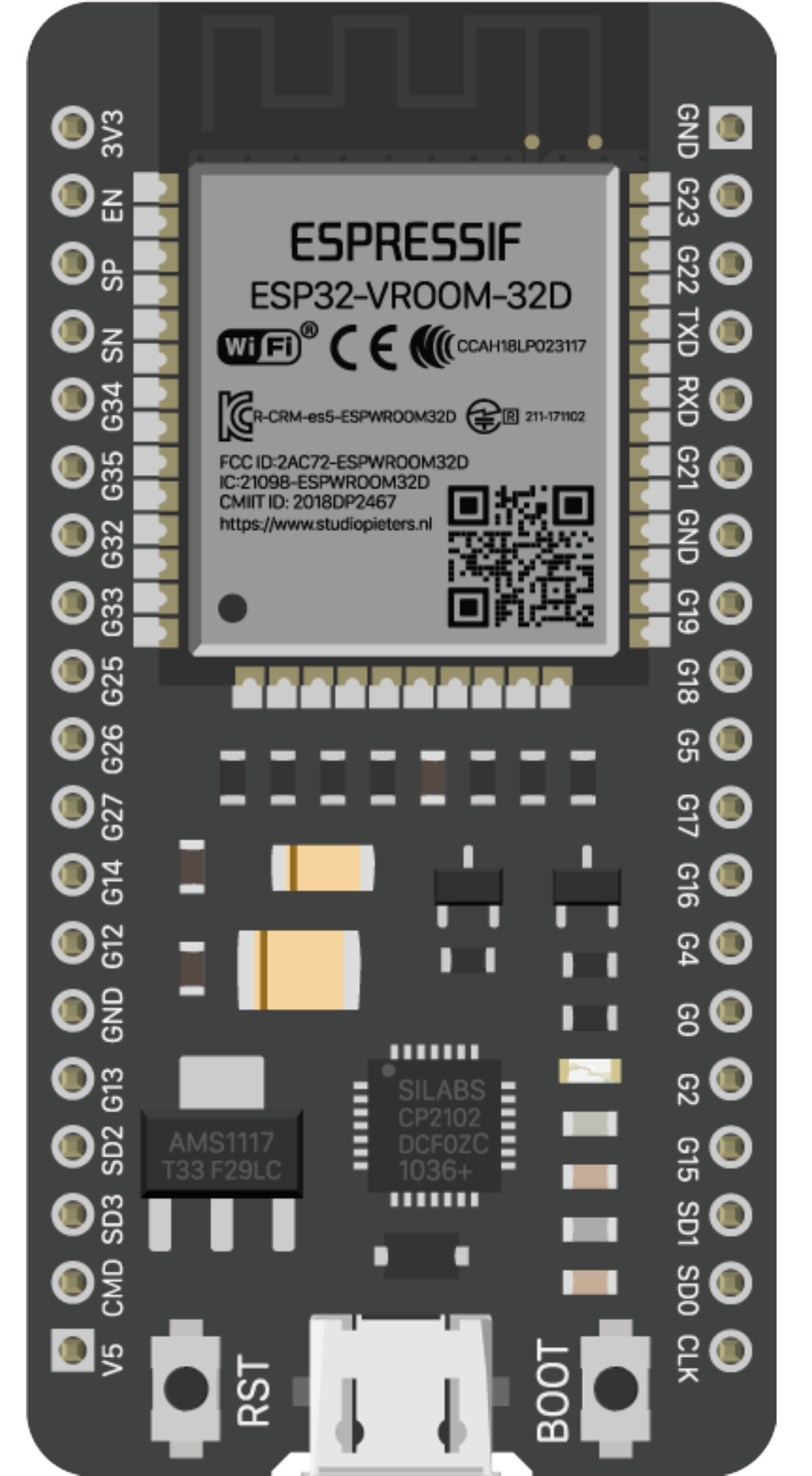
 Design with ESP32 - 38 pins in Cirkit Designer
Introduction
The ESP32 is a versatile and powerful microcontroller with integrated Wi-Fi and Bluetooth capabilities. It is widely used in Internet of Things (IoT) applications, smart home devices, and for prototyping wireless communication projects. The 38-pin variant provides ample GPIO pins for interfacing with a variety of sensors, actuators, and displays.
Explore Projects Built with ESP32 - 38 pins
ESP32-Based OLED Display Interface
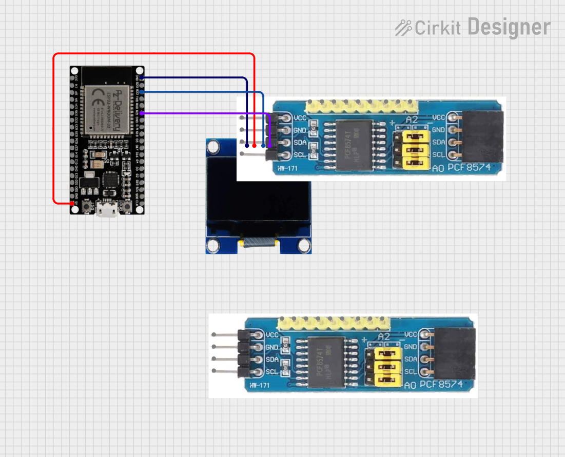
This circuit features an ESP32 microcontroller connected to an OLED 1.3" display. The ESP32's GPIO pins 21 and 22 are used for I2C communication (SDA and SCL respectively) with the OLED display. The display is powered by the 5V output from the ESP32, and both devices share a common ground.
 Open Project in Cirkit Designer
ESP32-Based Environmental Monitoring System with Ultrasonic, GPS, GSM, and Rain Sensor
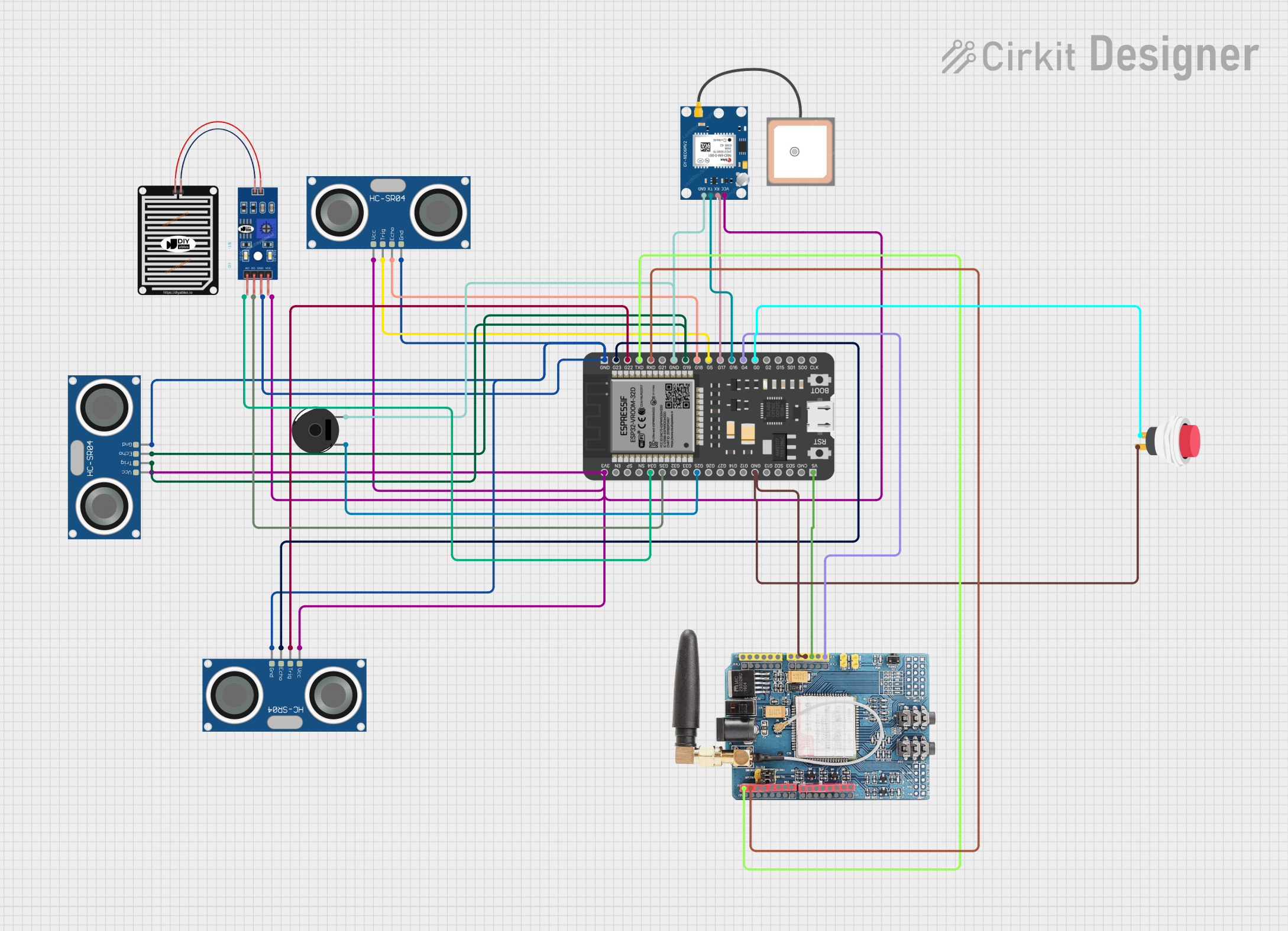
This circuit features an ESP32 microcontroller connected to multiple sensors and modules for environmental data collection and communication. It includes three HC-SR04 ultrasonic sensors for distance measurement, a rain sensor for detecting precipitation, a GPS NEO 6M module for location tracking, and a GSM SIM900 module for cellular communication. Additionally, there is a piezo buzzer for audio feedback and a push switch for user input, all sharing a common ground with the ESP32.
 Open Project in Cirkit Designer
ESP32-Based Wi-Fi Controlled LED System
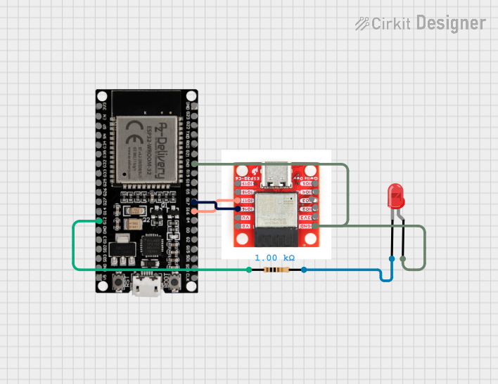
This circuit features two ESP32 microcontrollers communicating via UART, with one controlling an LED through a resistor. The primary ESP32 (ESP32 38 PINS) handles I2C communication and processes serial input to control the LED, while the secondary ESP32 (pocket esp32-c3) sends periodic data over UART.
 Open Project in Cirkit Designer
ESP32-Controlled Security System with Fingerprint Authentication and Servo Lock Mechanism
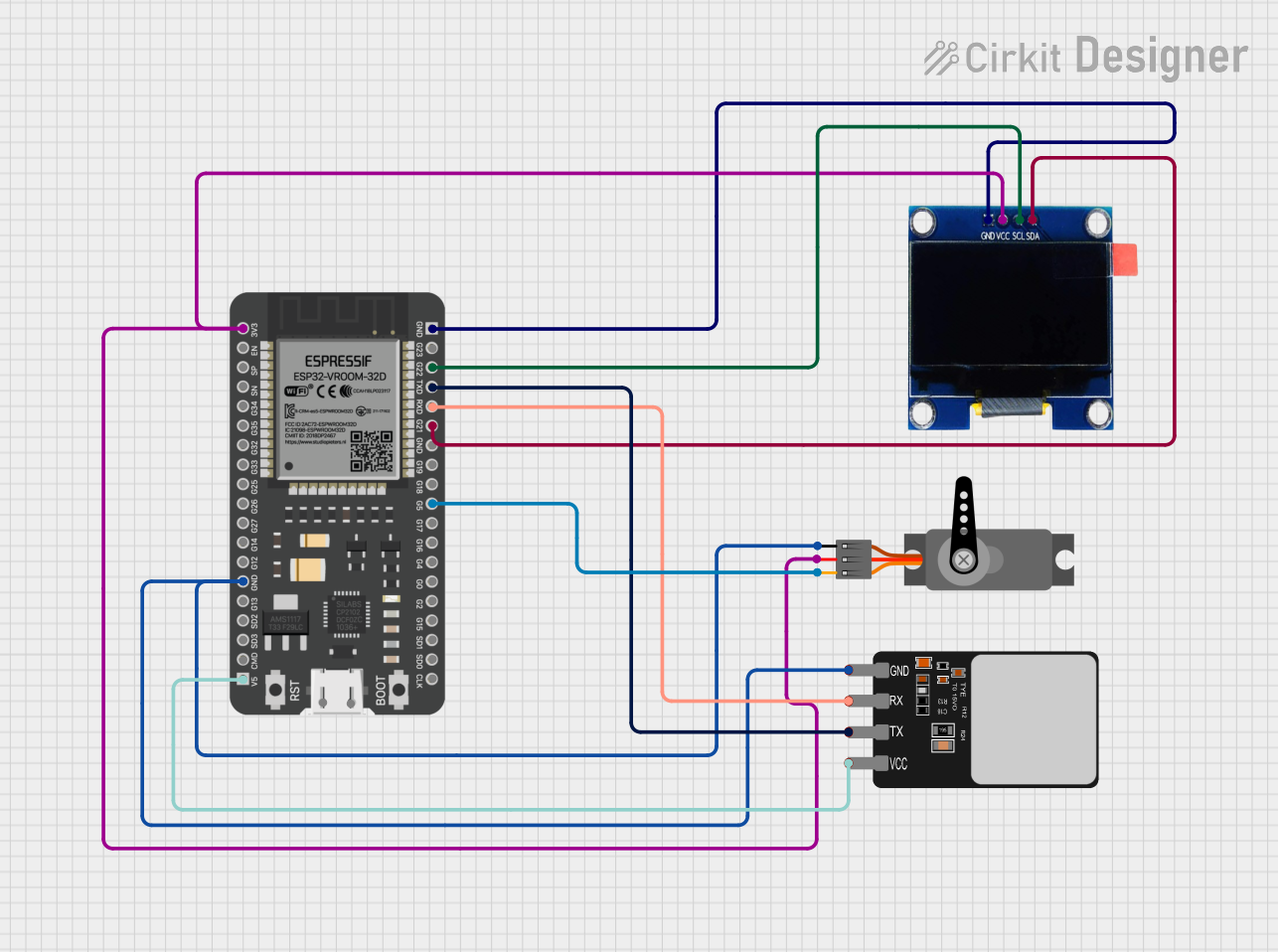
This circuit features an ESP32 microcontroller that interfaces with an OLED display, a servo motor, and a fingerprint scanner. The ESP32 provides power to the OLED and servo, and communicates with the OLED via I2C (SCL and SDA lines) and with the fingerprint scanner via serial communication (TX and RX lines). The servo is controlled by the ESP32 through a PWM signal, enabling the circuit to display information, authenticate users via fingerprints, and perform mechanical actions with the servo.
 Open Project in Cirkit Designer
Explore Projects Built with ESP32 - 38 pins

ESP32-Based OLED Display Interface
This circuit features an ESP32 microcontroller connected to an OLED 1.3" display. The ESP32's GPIO pins 21 and 22 are used for I2C communication (SDA and SCL respectively) with the OLED display. The display is powered by the 5V output from the ESP32, and both devices share a common ground.
 Open Project in Cirkit Designer
ESP32-Based Environmental Monitoring System with Ultrasonic, GPS, GSM, and Rain Sensor
This circuit features an ESP32 microcontroller connected to multiple sensors and modules for environmental data collection and communication. It includes three HC-SR04 ultrasonic sensors for distance measurement, a rain sensor for detecting precipitation, a GPS NEO 6M module for location tracking, and a GSM SIM900 module for cellular communication. Additionally, there is a piezo buzzer for audio feedback and a push switch for user input, all sharing a common ground with the ESP32.
 Open Project in Cirkit Designer
ESP32-Based Wi-Fi Controlled LED System
This circuit features two ESP32 microcontrollers communicating via UART, with one controlling an LED through a resistor. The primary ESP32 (ESP32 38 PINS) handles I2C communication and processes serial input to control the LED, while the secondary ESP32 (pocket esp32-c3) sends periodic data over UART.
 Open Project in Cirkit Designer
ESP32-Controlled Security System with Fingerprint Authentication and Servo Lock Mechanism
This circuit features an ESP32 microcontroller that interfaces with an OLED display, a servo motor, and a fingerprint scanner. The ESP32 provides power to the OLED and servo, and communicates with the OLED via I2C (SCL and SDA lines) and with the fingerprint scanner via serial communication (TX and RX lines). The servo is controlled by the ESP32 through a PWM signal, enabling the circuit to display information, authenticate users via fingerprints, and perform mechanical actions with the servo.
 Open Project in Cirkit Designer
Common Applications and Use Cases
- Smart home devices (e.g., light switches, thermostats)
- IoT sensor nodes
- Wearable electronics
- Wireless communication systems
- Robotics
Technical Specifications
Key Technical Details
- Microcontroller: Tensilica Xtensa® Dual-Core 32-bit LX6
- Operating Voltage: 3.3V
- Input Voltage (recommended): 5V
- Input Voltage (limit): 6-12V
- Digital I/O Pins: 34 (of which 12 can be configured as PWM outputs)
- Analog Input Pins: 18
- Analog Output Pins: 2 (DAC)
- Flash Memory: 4MB
- SRAM: 520 KB
- Clock Speed: 240 MHz
- Wi-Fi: 802.11 b/g/n
- Bluetooth: v4.2 BR/EDR and BLE
Pin Configuration and Descriptions
| Pin Number | Function | Description |
|---|---|---|
| 1-2 | GND | Ground |
| 3 | 3V3 | 3.3V power supply |
| 4-5 | EN | Chip enable. Active high. |
| 6-7 | VP, VN | Voltage for the internal Hall sensor |
| 8-9 | IO34, IO35 | Analog input (no pullup/pulldown) |
| 10-11 | IO32, IO33 | General purpose IO with DAC |
| 12-13 | IO25, IO26 | General purpose IO with DAC |
| 14-23 | IO14-IO23 | General purpose IO |
| 24-25 | IO13, IO12 | General purpose IO (used for boot mode sel.) |
| 26-27 | IO9, IO10 | General purpose IO (not exposed in all mods) |
| 28-29 | IO11, IO0 | General purpose IO (used for boot mode sel.) |
| 30 | GND | Ground |
| 31 | 5V | 5V power supply |
| 32-33 | TX0, RX0 | UART0 |
| 34-35 | IO1, IO3 | UART0; IO1 (TX), IO3 (RX) |
| 36-37 | IO21, IO19 | General purpose IO |
| 38 | IO18 | General purpose IO |
Usage Instructions
How to Use the ESP32 in a Circuit
- Powering the ESP32: Connect a 5V power supply to the 5V and GND pins. Alternatively, you can use a 3.3V supply directly to the 3V3 pin.
- Programming the ESP32: Use a micro USB cable to connect the ESP32 to your computer. Install the necessary drivers and use the Arduino IDE or ESP-IDF for programming.
- Connecting I/O Devices: Interface sensors, actuators, or other peripherals to the GPIO pins. Ensure that the voltage levels are compatible with the ESP32's 3.3V logic.
Important Considerations and Best Practices
- Always check the power requirements of peripherals to avoid damaging the ESP32.
- Use a logic level converter if interfacing with 5V devices.
- Avoid using IO9 and IO10 as they are not exposed in all modules.
- IO34 and IO35 cannot be used as digital outputs.
- When using Wi-Fi or Bluetooth, ensure that the antenna area is not obstructed.
Troubleshooting and FAQs
Common Issues
- ESP32 not booting: Ensure that the boot mode is correctly set by checking the IO0 pin.
- Wi-Fi/Bluetooth not functioning: Verify that the antenna is not obstructed and that the correct drivers are installed.
- Unexpected resets: Check the power supply for stability and sufficient current.
Solutions and Tips for Troubleshooting
- Use a multimeter to check the voltage levels at different points in the circuit.
- Ensure that the GPIO pins are configured correctly in your code.
- Consult the ESP32 datasheet for detailed information on pin functions and limitations.
Example Code for Arduino UNO
#include <WiFi.h>

// Replace with your network credentials
const char* ssid = "your_SSID";
const char* password = "your_PASSWORD";

void setup() {
  Serial.begin(115200);

  // Connect to Wi-Fi
  WiFi.begin(ssid, password);
  while (WiFi.status() != WL_CONNECTED) {
    delay(500);
    Serial.println("Connecting to WiFi...");
  }
  Serial.println("Connected to WiFi");
}

void loop() {
  // Your code here
}
Code Comments
#include <WiFi.h>: Include the Wi-Fi library for ESP32.const char* ssid: Replaceyour_SSIDwith your Wi-Fi network name.const char* password: Replaceyour_PASSWORDwith your Wi-Fi network password.Serial.begin(115200): Initialize serial communication at 115200 baud rate.WiFi.begin(ssid, password): Start Wi-Fi connection with SSID and password.WiFi.status(): Check the status of the Wi-Fi connection.Serial.println(): Print messages to the serial monitor.
Remember to adjust the SSID and password to match your Wi-Fi network's credentials before uploading the code to the ESP32.