How to Use LDR Board V1: Examples, Pinouts, and Specs
Introduction
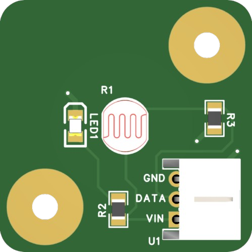
The LDR Board V1 by NeoOrbit Dynamics (Part ID: 000001) is a compact and efficient light-sensing module designed to detect and respond to varying light intensities. At its core, the board features a Light Dependent Resistor (LDR) that adjusts its resistance based on the ambient light level. This makes it an ideal choice for applications requiring light detection and automation.
Explore Projects Built with LDR Board V1
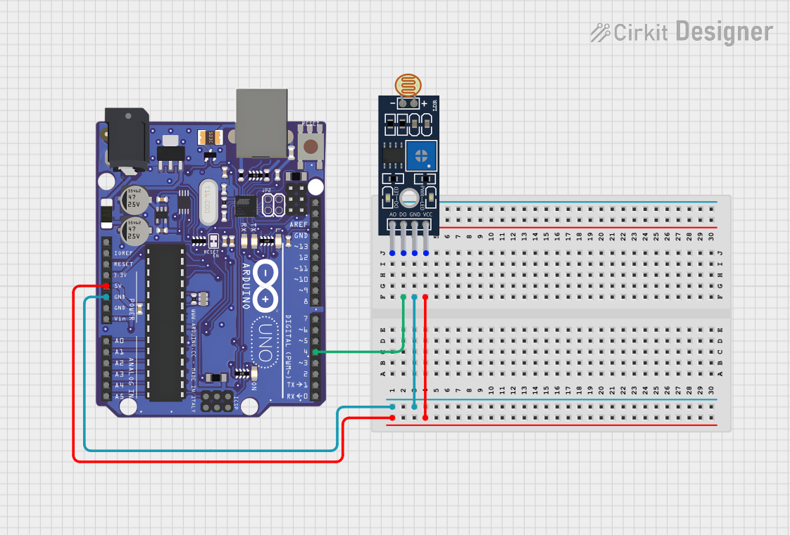
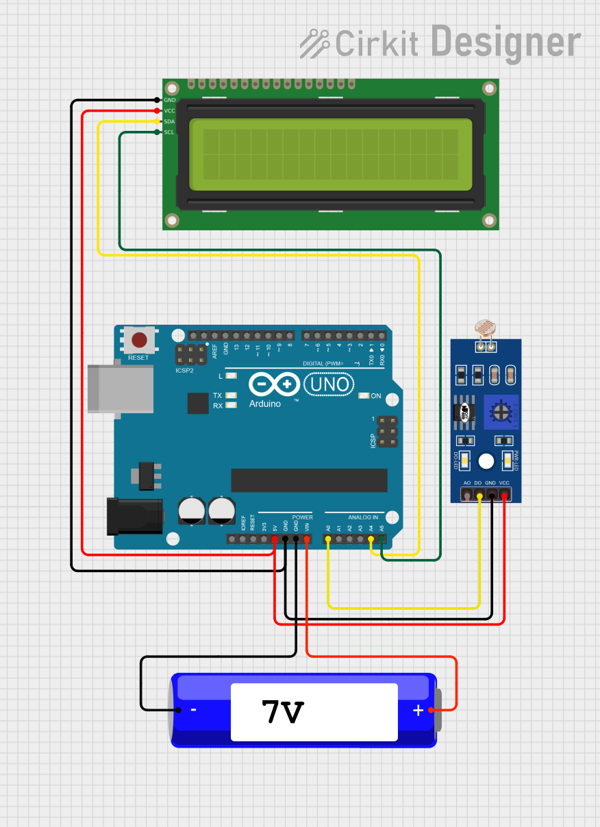
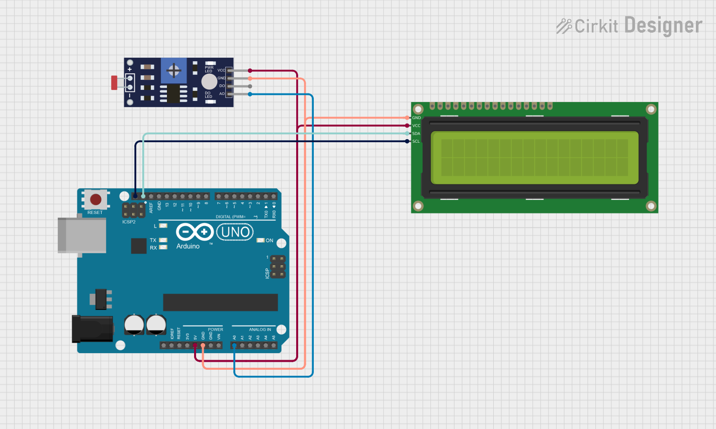
Explore Projects Built with LDR Board V1
Common Applications and Use Cases
- Automatic street lighting systems
- Light-sensitive alarms and security systems
- Brightness adjustment in displays
- Solar tracking systems
- DIY electronics and Arduino-based projects
Technical Specifications
The following table outlines the key technical details of the LDR Board V1:
| Parameter | Specification |
|---|---|
| Operating Voltage | 3.3V to 5V DC |
| Output Type | Analog voltage (proportional to light intensity) |
| LDR Resistance Range | 1 kΩ (bright light) to 1 MΩ (darkness) |
| Board Dimensions | 25mm x 20mm x 5mm |
| Operating Temperature | -10°C to 50°C |
| Power Consumption | < 10 mW |
Pin Configuration and Descriptions
The LDR Board V1 has a simple 3-pin interface:
| Pin | Name | Description |
|---|---|---|
| 1 | VCC | Power supply input (3.3V to 5V DC) |
| 2 | GND | Ground connection |
| 3 | OUT | Analog output voltage proportional to light intensity |
Usage Instructions
How to Use the LDR Board V1 in a Circuit
- Power the Board: Connect the
VCCpin to a 3.3V or 5V DC power source and theGNDpin to the ground of your circuit. - Read the Output: Connect the
OUTpin to an analog input pin of a microcontroller (e.g., Arduino UNO) or an analog-to-digital converter (ADC) to measure the light intensity. - Interpret the Output: The output voltage on the
OUTpin varies with light intensity:- Higher voltage indicates brighter light.
- Lower voltage indicates dimmer light or darkness.
Important Considerations and Best Practices
- Avoid Direct Sunlight: Prolonged exposure to direct sunlight may degrade the LDR's performance over time.
- Use a Pull-Down Resistor: If the output is noisy, consider adding a pull-down resistor (e.g., 10 kΩ) between the
OUTpin andGNDto stabilize the signal. - Shield from Electrical Noise: Place the board away from high-frequency noise sources to ensure accurate readings.
- Calibrate for Your Application: Depending on your use case, you may need to map the analog output to specific light intensity levels.
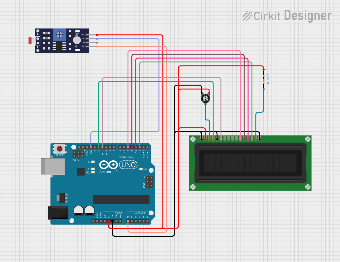
Example: Connecting to an Arduino UNO
Below is an example of how to use the LDR Board V1 with an Arduino UNO to read light intensity and display the value in the Serial Monitor.
// Define the analog pin connected to the LDR Board V1
const int ldrPin = A0; // Connect the OUT pin of the LDR Board to A0

void setup() {
  Serial.begin(9600); // Initialize serial communication at 9600 baud
  pinMode(ldrPin, INPUT); // Set the LDR pin as an input
}

void loop() {
  int ldrValue = analogRead(ldrPin); // Read the analog value from the LDR Board
  float voltage = (ldrValue / 1023.0) * 5.0; // Convert the reading to voltage

  // Print the light intensity value to the Serial Monitor
  Serial.print("LDR Value: ");
  Serial.print(ldrValue);
  Serial.print(" | Voltage: ");
  Serial.print(voltage);
  Serial.println(" V");

  delay(500); // Wait for 500ms before the next reading
}
Troubleshooting and FAQs
Common Issues and Solutions
No Output Voltage
- Cause: Incorrect wiring or insufficient power supply.
- Solution: Verify that the
VCCandGNDpins are properly connected to a 3.3V or 5V power source.
Fluctuating Output
- Cause: Electrical noise or unstable power supply.
- Solution: Add a pull-down resistor (e.g., 10 kΩ) between the
OUTpin andGND. Ensure the power supply is stable.
Output Voltage Does Not Change with Light
- Cause: LDR is damaged or obstructed.
- Solution: Inspect the LDR for physical damage or dirt. Clean or replace the LDR if necessary.
Arduino Reads Incorrect Values
- Cause: Incorrect analog pin configuration or faulty connections.
- Solution: Double-check the wiring and ensure the correct analog pin is defined in the code.
FAQs
Q: Can the LDR Board V1 be used outdoors?
A: Yes, but it should be housed in a weatherproof enclosure to protect it from moisture and extreme temperatures.
Q: What is the maximum distance between the LDR Board and the microcontroller?
A: For best performance, keep the distance under 1 meter to minimize signal degradation.
Q: Can I use the LDR Board V1 with a 3.3V microcontroller?
A: Yes, the board is compatible with both 3.3V and 5V systems.
Q: How do I calibrate the LDR Board for specific light levels?
A: Use the analog output values to map the light intensity range in your application. You can adjust thresholds in your code based on the output readings.
This concludes the documentation for the LDR Board V1. For further assistance, please contact NeoOrbit Dynamics support.