How to Use HW-601: Examples, Pinouts, and Specs
Introduction
The HW-601 is a versatile electronic component widely used in signal processing and control systems. Its compact design makes it ideal for integration into a variety of devices, ranging from consumer electronics to industrial equipment. The HW-601 is known for its reliability, ease of use, and compatibility with numerous microcontroller platforms, making it a popular choice for engineers and hobbyists alike.
Explore Projects Built with HW-601


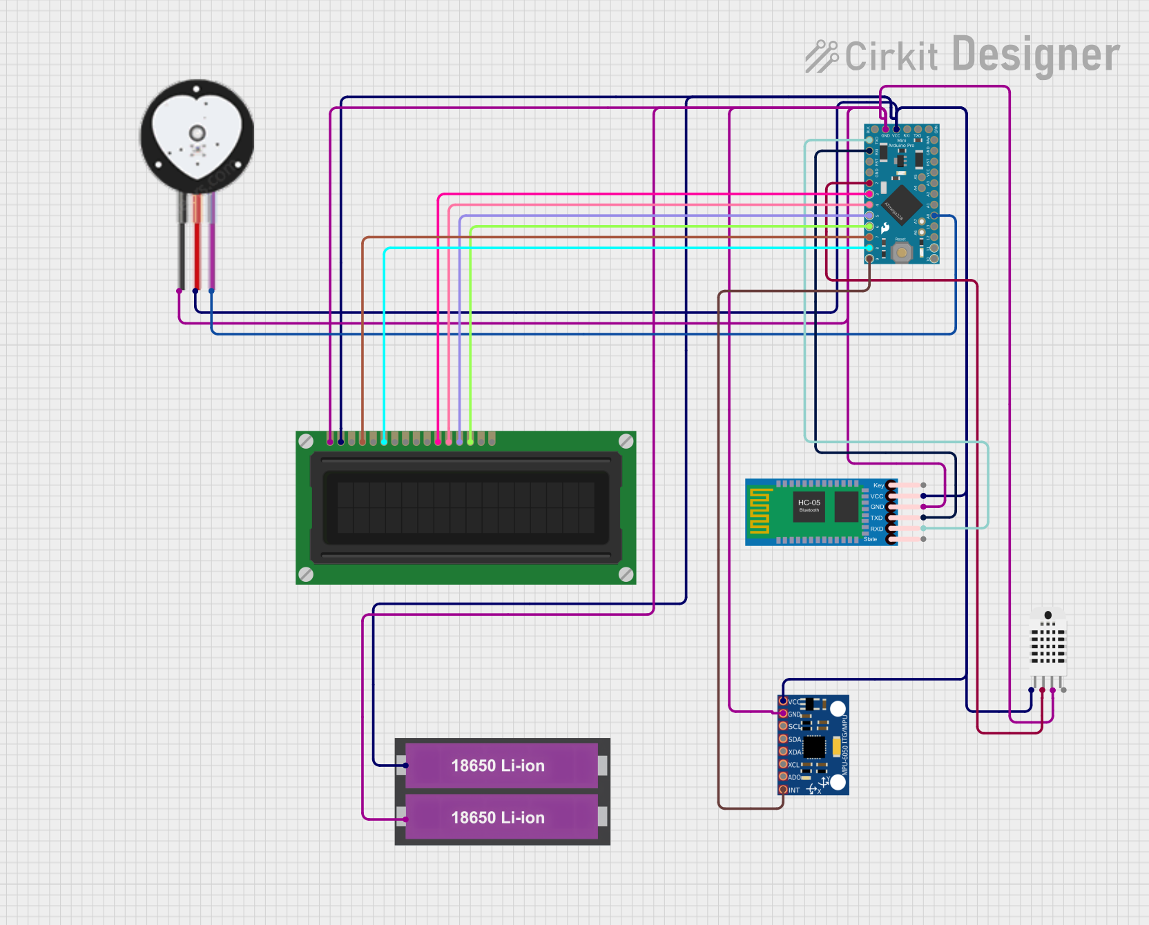
Explore Projects Built with HW-601
Common Applications
- Signal amplification and conditioning
- Control systems in industrial automation
- Audio processing circuits
- Sensor interfacing and data acquisition
- Embedded systems and IoT devices
Technical Specifications
The HW-601 is designed to operate efficiently in a wide range of applications. Below are its key technical details:
General Specifications
| Parameter | Value |
|---|---|
| Operating Voltage | 3.3V to 5V |
| Maximum Current | 50mA |
| Signal Frequency Range | 20Hz to 20kHz |
| Operating Temperature | -20°C to 85°C |
| Dimensions | 25mm x 15mm x 5mm |
Pin Configuration
The HW-601 features a simple pinout for easy integration into circuits. Below is the pin configuration:
| Pin Number | Pin Name | Description |
|---|---|---|
| 1 | VCC | Power supply input (3.3V to 5V) |
| 2 | GND | Ground connection |
| 3 | IN | Signal input |
| 4 | OUT | Signal output |
| 5 | EN | Enable pin (active HIGH to enable the component) |
Usage Instructions
The HW-601 is straightforward to use in a variety of circuits. Follow the steps below to integrate it into your project:
Basic Circuit Connection
- Power Supply: Connect the
VCCpin to a 3.3V or 5V power source and theGNDpin to the ground of your circuit. - Signal Input: Feed the input signal to the
INpin. Ensure the signal voltage is within the operating range of the HW-601. - Signal Output: Connect the
OUTpin to the desired load or the next stage of your circuit. - Enable Pin: To activate the HW-601, set the
ENpin HIGH. If unused, connect it toVCCto keep the component enabled.
Important Considerations
- Power Supply: Ensure a stable power supply to avoid noise or instability in the output signal.
- Signal Conditioning: Use appropriate resistors or capacitors if the input signal requires filtering or impedance matching.
- Thermal Management: Operate the HW-601 within its specified temperature range to prevent overheating.
Example: Using HW-601 with Arduino UNO
The HW-601 can be easily interfaced with an Arduino UNO for signal processing tasks. Below is an example of how to use it:
Circuit Connections
- Connect the
VCCpin of the HW-601 to the 5V pin of the Arduino. - Connect the
GNDpin of the HW-601 to the GND pin of the Arduino. - Connect the
INpin to an analog signal source (e.g., a sensor). - Connect the
OUTpin to an analog input pin on the Arduino (e.g., A0). - Connect the
ENpin to a digital output pin on the Arduino (e.g., D2).
Arduino Code
// Example code to read and process a signal using the HW-601 with Arduino UNO

const int enablePin = 2;  // Digital pin connected to HW-601 EN pin
const int inputPin = A0;  // Analog pin connected to HW-601 OUT pin

void setup() {
  pinMode(enablePin, OUTPUT);  // Set enable pin as output
  digitalWrite(enablePin, HIGH);  // Enable the HW-601
  Serial.begin(9600);  // Initialize serial communication
}

void loop() {
  int signalValue = analogRead(inputPin);  // Read the signal from HW-601
  float voltage = (signalValue / 1023.0) * 5.0;  // Convert to voltage

  // Print the signal voltage to the Serial Monitor
  Serial.print("Signal Voltage: ");
  Serial.print(voltage);
  Serial.println(" V");

  delay(500);  // Wait for 500ms before the next reading
}
Troubleshooting and FAQs
Common Issues
No Output Signal
- Cause: The
ENpin is not set HIGH. - Solution: Ensure the
ENpin is connected toVCCor a HIGH digital output.
- Cause: The
Distorted Output Signal
- Cause: Input signal exceeds the operating range.
- Solution: Verify the input signal voltage and use a voltage divider if necessary.
Component Overheating
- Cause: Operating outside the specified voltage or temperature range.
- Solution: Check the power supply and ensure proper thermal management.
Unstable Output
- Cause: Noise in the power supply or input signal.
- Solution: Use decoupling capacitors near the
VCCandGNDpins.
FAQs
Q1: Can the HW-601 operate at 12V?
A1: No, the HW-601 is designed to operate within a voltage range of 3.3V to 5V. Exceeding this range may damage the component.
Q2: Is the HW-601 compatible with 3.3V microcontrollers?
A2: Yes, the HW-601 can operate at 3.3V, making it compatible with 3.3V microcontrollers like the ESP32 or STM32.
Q3: Can I leave the EN pin unconnected?
A3: No, the EN pin must be connected to VCC or a HIGH signal to enable the component. Leaving it unconnected will disable the HW-601.
Q4: What is the maximum input signal voltage?
A4: The input signal voltage should not exceed the operating voltage of the HW-601 (3.3V or 5V). Use a voltage divider if necessary.