How to Use Dual Power Automatic Transfer Switch: Examples, Pinouts, and Specs
Introduction
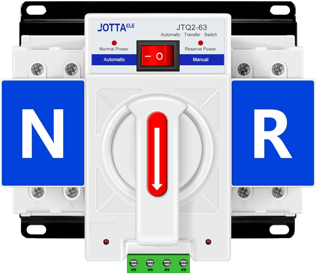
The Dual Power Automatic Transfer Switch (ATS) by JOTTAELE, model ATS CB-2P 63A 110V, is an essential component in electrical systems where continuous power supply is critical. It is designed to automatically switch between two power sources, such as the mains power and a backup generator, to ensure an uninterrupted power supply. This ATS is commonly used in residential, commercial, and industrial settings where power continuity is necessary for safety, data integrity, or operational consistency.
Explore Projects Built with Dual Power Automatic Transfer Switch
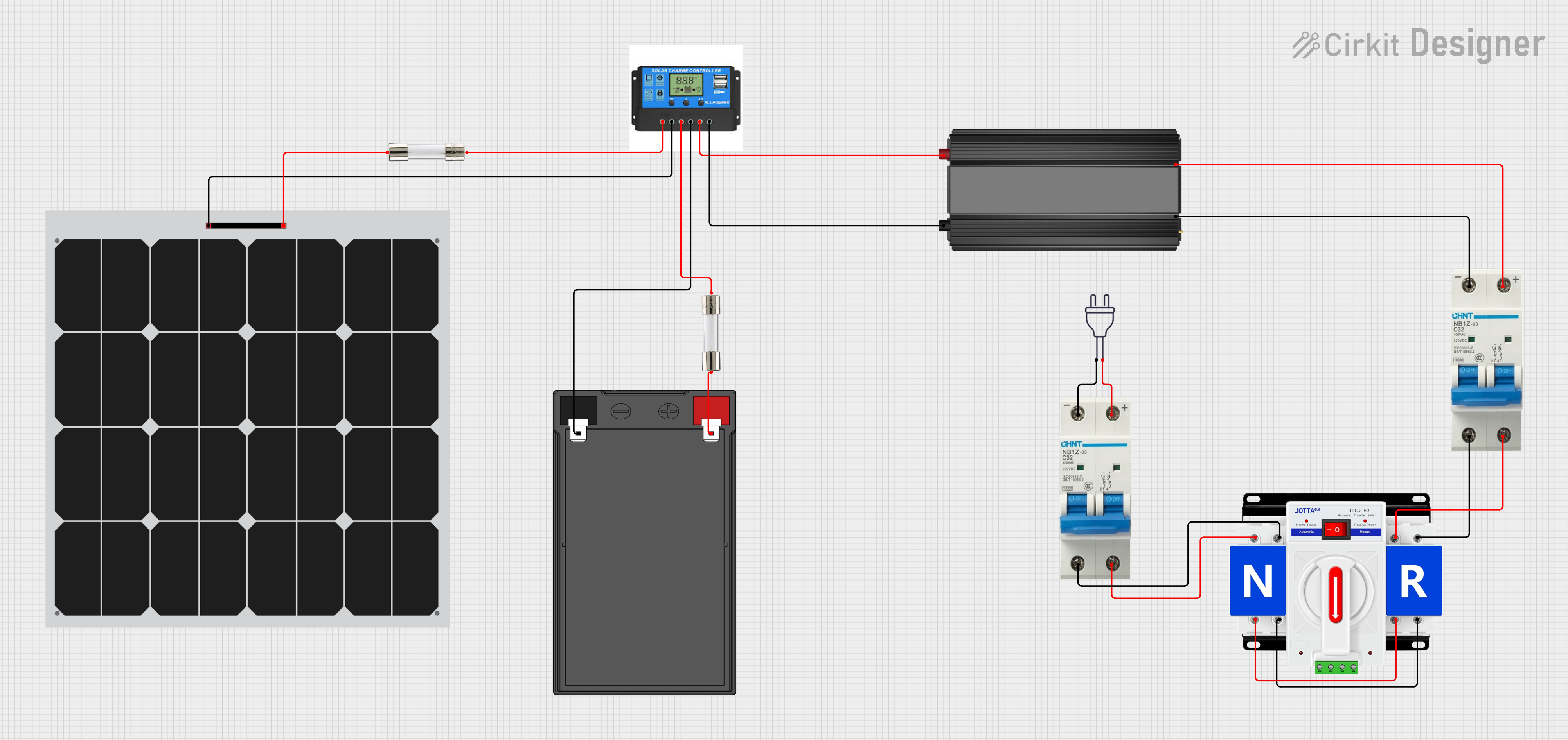

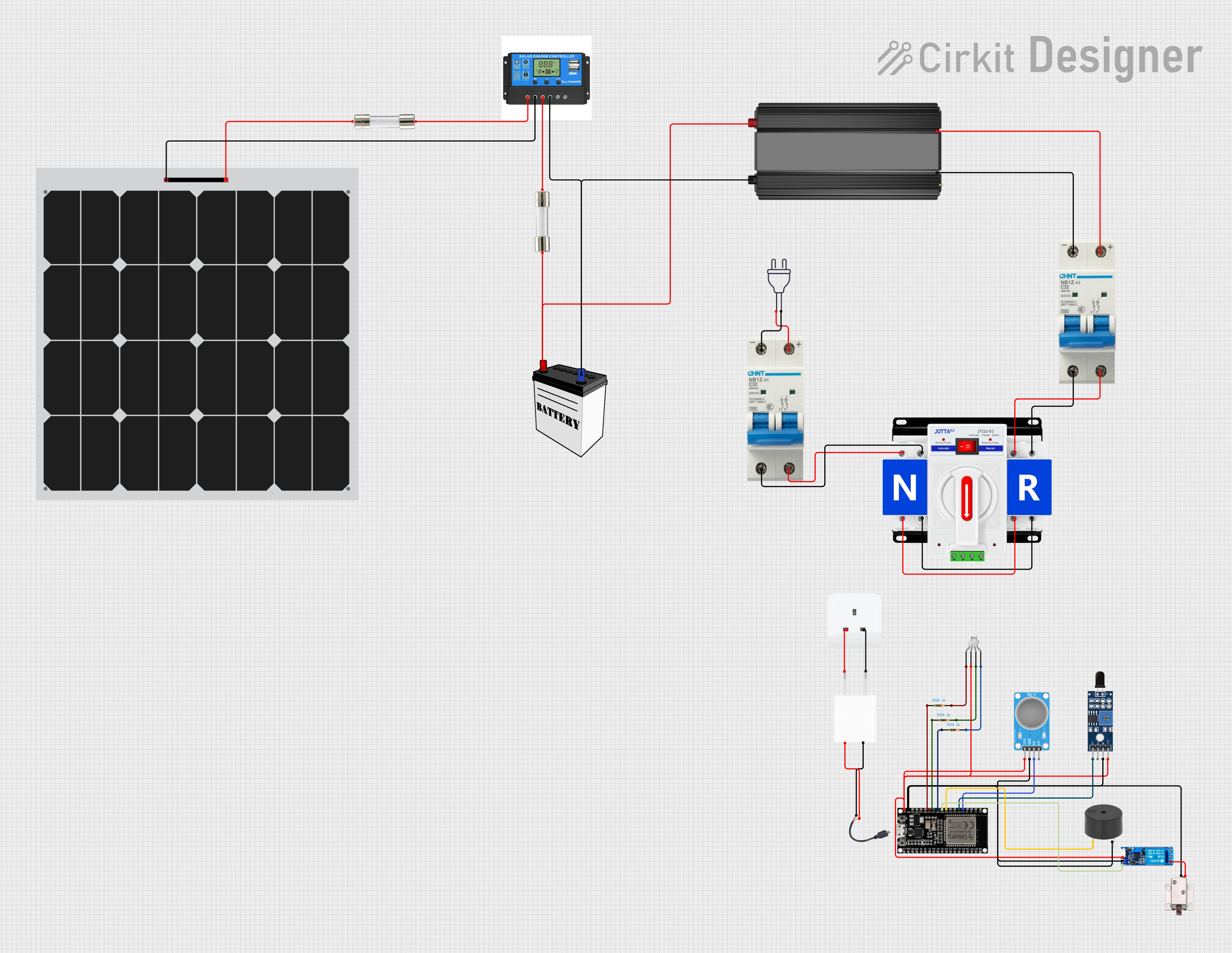
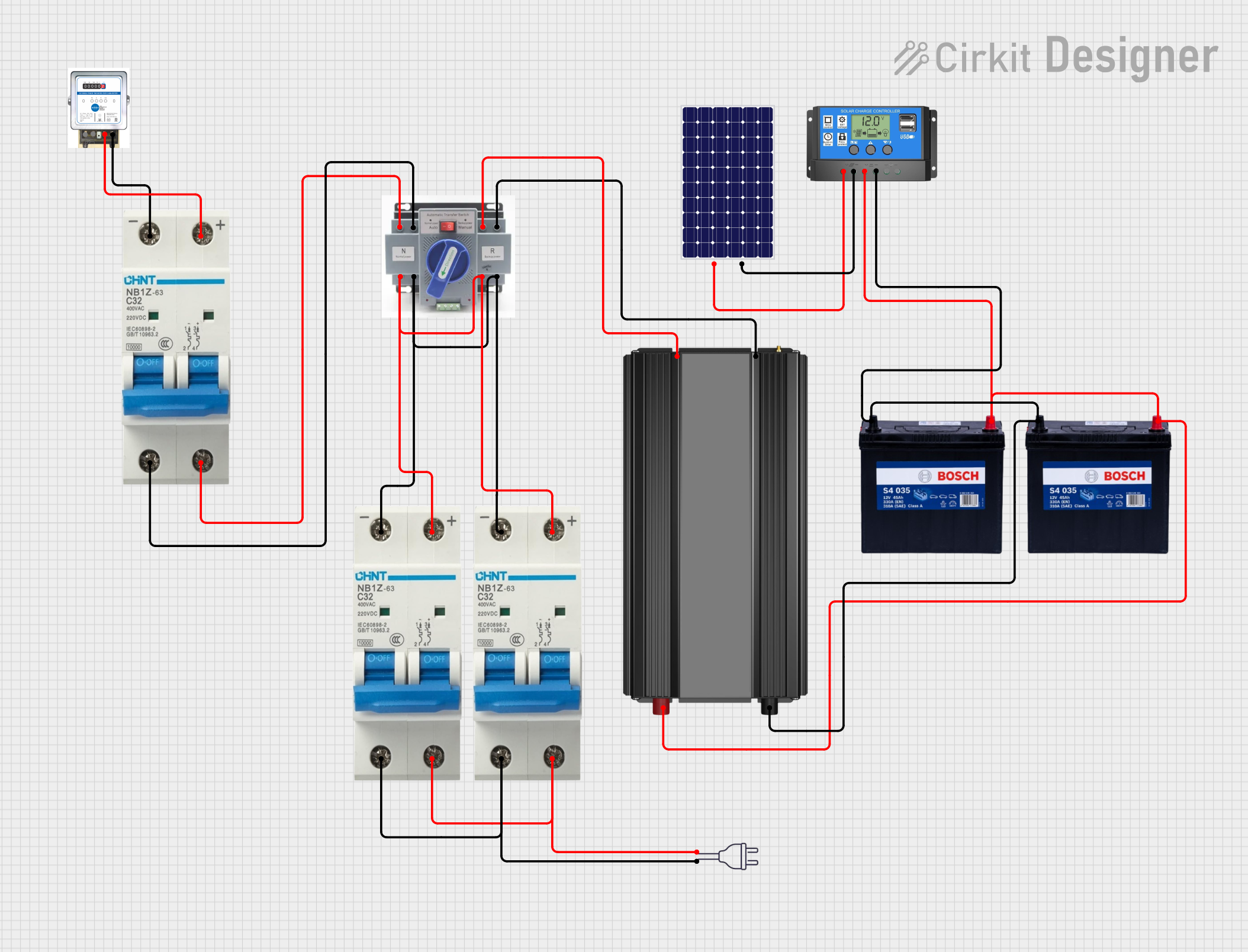
Explore Projects Built with Dual Power Automatic Transfer Switch
Common Applications and Use Cases
- Emergency power systems in hospitals and data centers
- Backup power for residential and commercial buildings
- Industrial processes that require a constant power supply
- Critical infrastructure such as telecommunications and transportation
Technical Specifications
Key Technical Details
| Specification | Value |
|---|---|
| Rated Voltage | 110V AC |
| Rated Current | 63A |
| Frequency | 50/60Hz |
| Number of Poles | 2 |
| Control Power Voltage | 110V AC |
| Transfer Time | ≤ 2 seconds |
| Operating Temperature | -20°C to +65°C |
Pin Configuration and Descriptions
| Pin Number | Description |
|---|---|
| 1 | Input from Power Source 1 |
| 2 | Input from Power Source 2 |
| 3 | Output to Load |
| 4 | Neutral Connection |
| 5 | Control Power Input |
| 6 | Common Alarm Output |
| 7 | Source 1 Failure Indicator |
| 8 | Source 2 Failure Indicator |
Usage Instructions
How to Use the Component in a Circuit
- Installation: Ensure that the ATS is installed by a qualified electrician, following all local codes and standards.
- Wiring: Connect the two power sources to pins 1 and 2, the load to pin 3, and the neutral to pin 4. The control power should be connected to pin 5.
- Testing: After installation, test the ATS by simulating failure conditions to ensure it operates correctly.
- Operation: The ATS will automatically monitor the power sources and switch to the backup source if the primary source fails.
Important Considerations and Best Practices
- Ensure that the ATS's rated current and voltage match the requirements of your electrical system.
- Regularly test and maintain the ATS to ensure reliability.
- Do not exceed the maximum operating temperature to prevent damage to the ATS.
- Use appropriate cable sizes to handle the rated current without overheating.
Troubleshooting and FAQs
Common Issues
- ATS does not switch to the backup source: Check the control power supply and connections to the ATS. Ensure that both power sources are available and within the acceptable voltage range.
- Delayed switching: If the transfer time is longer than expected, inspect the ATS for any signs of wear or damage. Consult the manufacturer's documentation for detailed troubleshooting steps.
FAQs
Q: Can the ATS be used with power sources of different voltages? A: No, the ATS CB-2P 63A 110V is designed for use with 110V AC power sources only.
Q: Is there a manual override function? A: Yes, the ATS typically includes a manual override switch. Refer to the manufacturer's manual for instructions on how to operate it.
Q: How often should the ATS be tested? A: It is recommended to test the ATS every six months or according to the manufacturer's guidelines.
Q: What is the warranty period for the ATS? A: Warranty information can vary. Please contact JOTTAELE or the distributor from which the ATS was purchased for specific warranty details.
Example Arduino UNO Connection (If Applicable)
This ATS is not directly interfaced with microcontrollers like the Arduino UNO, as it operates at high voltages and currents that are not suitable for direct control by low-voltage electronics. However, an Arduino can be used to monitor the status of the ATS through auxiliary contacts or indicators if available. Always ensure that any connections to the Arduino are made through appropriate interfacing components like relays or optoisolators to ensure safety and prevent damage to the microcontroller.
// Example code to monitor ATS status using Arduino UNO
// Note: This is a hypothetical example. Actual implementation may vary.

const int source1FailurePin = 2; // ATS Source 1 Failure Indicator connected to digital pin 2
const int source2FailurePin = 3; // ATS Source 2 Failure Indicator connected to digital pin 3

void setup() {
  pinMode(source1FailurePin, INPUT_PULLUP); // Set the pin as input with internal pull-up
  pinMode(source2FailurePin, INPUT_PULLUP); // Set the pin as input with internal pull-up
  Serial.begin(9600); // Start serial communication at 9600 baud rate
}

void loop() {
  bool source1Failure = digitalRead(source1FailurePin) == LOW; // Read the status of source 1
  bool source2Failure = digitalRead(source2FailurePin) == LOW; // Read the status of source 2

  if (source1Failure) {
    Serial.println("Source 1 has failed. ATS should switch to Source 2.");
  }
  if (source2Failure) {
    Serial.println("Source 2 has failed. Check backup power source.");
  }

  delay(1000); // Wait for 1 second before reading the status again
}
Please note that the above code is for illustrative purposes only and should be adapted to the specific ATS model and its features. Always consult the ATS datasheet and manufacturer's documentation for accurate information on interfacing and monitoring the ATS.