How to Use LT431: Examples, Pinouts, and Specs
Introduction
The LT431, manufactured by aaa with the part ID TL431, is a precision voltage reference and adjustable shunt regulator. It is designed to provide a stable reference voltage, making it an essential component in power supply circuits. The LT431 ensures a constant output voltage, even in the presence of fluctuations in input voltage or load conditions. Its versatility and reliability make it a popular choice in a wide range of applications.
Explore Projects Built with LT431


Explore Projects Built with LT431
Common Applications and Use Cases
- Voltage regulation in power supply circuits
- Precision current limiting
- Adjustable voltage references
- Feedback control in switching power supplies
- Battery chargers and LED drivers
Technical Specifications
The LT431 is a highly precise and adjustable component. Below are its key technical specifications:
| Parameter | Value |
|---|---|
| Reference Voltage (Vref) | 2.495V (typical) |
| Adjustable Output Voltage | 2.495V to 36V |
| Operating Current Range | 1mA to 100mA |
| Cathode Voltage (Vka) | Up to 37V |
| Reference Voltage Tolerance | ±0.5% (typical) |
| Temperature Range | -40°C to +125°C |
| Package Options | TO-92, SOT-23, SOIC-8 |
Pin Configuration and Descriptions
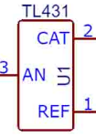
The LT431 typically comes in a 3-pin package. Below is the pinout and description:
| Pin Number | Pin Name | Description |
|---|---|---|
| 1 | Reference | Input for the reference voltage (Vref). Used to set the output voltage. |
| 2 | Cathode | Connects to the negative terminal of the circuit. Acts as the output. |
| 3 | Anode | Connects to the positive terminal of the circuit. Provides the input voltage. |
Usage Instructions
The LT431 is straightforward to use in a circuit. Below are the steps and considerations for its implementation:
Basic Circuit Configuration
To use the LT431 as an adjustable shunt regulator:
- Connect the Anode to the positive supply voltage.
- Connect the Cathode to the load or output voltage.
- Use a resistor divider network to set the desired output voltage. The voltage at the Reference pin should be 2.495V for proper operation.
Example Circuit
Below is a basic circuit diagram for setting the output voltage:
   +Vcc
     |
     R1
     |
     +---- Reference (Pin 1)
     |     LT431
     R2    Cathode (Pin 2) ----> Vout
     |     Anode (Pin 3)
    GND
The output voltage is determined by the resistor divider: [ V_{out} = V_{ref} \times \left(1 + \frac{R1}{R2}\right) ]
Important Considerations
- Ensure that the input voltage (Vka) does not exceed 37V.
- Select resistors with low tolerance for better accuracy in setting the output voltage.
- Use a bypass capacitor near the LT431 to improve stability in noisy environments.
- Avoid exceeding the maximum cathode current of 100mA to prevent damage.
Arduino UNO Example
The LT431 can be used with an Arduino UNO to monitor or control voltage levels. Below is an example code snippet to read the output voltage using the Arduino's ADC:
// Define the analog pin connected to the LT431 output
const int analogPin = A0;

// Reference voltage of the Arduino (typically 5V)
const float vRef = 5.0;

// ADC resolution (10-bit for Arduino UNO)
const int adcResolution = 1024;

void setup() {
  Serial.begin(9600); // Initialize serial communication
}

void loop() {
  int adcValue = analogRead(analogPin); // Read the ADC value
  float outputVoltage = (adcValue * vRef) / adcResolution; // Calculate voltage

  // Print the output voltage to the serial monitor
  Serial.print("Output Voltage: ");
  Serial.print(outputVoltage);
  Serial.println(" V");

  delay(1000); // Wait for 1 second before the next reading
}
Notes for Arduino Users
- Use a voltage divider if the LT431 output exceeds the Arduino's ADC input range (5V).
- Ensure proper grounding between the LT431 circuit and the Arduino.
Troubleshooting and FAQs
Common Issues and Solutions
| Issue | Possible Cause | Solution |
|---|---|---|
| Output voltage is unstable | Insufficient bypass capacitance | Add a capacitor (e.g., 0.1µF) near the LT431. |
| Output voltage is incorrect | Incorrect resistor values in the divider | Verify and recalculate R1 and R2 values. |
| LT431 overheating | Exceeding maximum cathode current (100mA) | Reduce the load current or increase resistor values. |
| No output voltage | Incorrect pin connections | Double-check the pin configuration. |
FAQs
Q: Can the LT431 be used for high-current applications?
A: No, the LT431 is designed for currents up to 100mA. For higher currents, use an external transistor with the LT431 to handle the load.
Q: How do I improve the accuracy of the output voltage?
A: Use precision resistors with low tolerance (e.g., 0.1%) in the resistor divider network. Additionally, ensure the LT431 operates within its specified temperature range.
Q: Can the LT431 be used as a fixed voltage reference?
A: Yes, by connecting the Reference pin directly to the Cathode pin, the LT431 provides a fixed 2.495V reference.
Q: What happens if the input voltage exceeds 37V?
A: Exceeding the maximum cathode voltage (Vka) can damage the LT431. Use a zener diode or other protection circuit to prevent overvoltage.
This concludes the documentation for the LT431. For further assistance, refer to the manufacturer's datasheet or contact technical support.