How to Use ESP32 (30 pin): Examples, Pinouts, and Specs
Introduction
The ESP32 is a powerful and versatile microcontroller designed for IoT (Internet of Things) applications and embedded systems. It features built-in Wi-Fi and Bluetooth capabilities, making it an excellent choice for projects requiring wireless communication. With its 30-pin configuration, the ESP32 provides a wide range of GPIO (General Purpose Input/Output) pins, ADC (Analog-to-Digital Converter) channels, PWM (Pulse Width Modulation) outputs, and other peripherals, enabling developers to create complex and feature-rich applications.
Explore Projects Built with ESP32 (30 pin)


Explore Projects Built with ESP32 (30 pin)
Common Applications and Use Cases
- IoT devices and smart home automation
- Wireless sensor networks
- Wearable technology
- Robotics and drones
- Data logging and remote monitoring
- Industrial automation and control systems
Technical Specifications
The ESP32 (30 pin) microcontroller is equipped with robust hardware and features. Below are its key technical specifications:
Key Technical Details
- Processor: Dual-core Xtensa® 32-bit LX6 microprocessor
- Clock Speed: Up to 240 MHz
- Flash Memory: 4 MB (varies by model)
- SRAM: 520 KB
- Wi-Fi: 802.11 b/g/n (2.4 GHz)
- Bluetooth: v4.2 BR/EDR and BLE
- Operating Voltage: 3.3V
- Input Voltage Range: 5V (via USB) or 3.3V (via VIN pin)
- GPIO Pins: 30 pins (including ADC, DAC, PWM, I2C, SPI, UART)
- ADC Resolution: 12-bit
- DAC Resolution: 8-bit
- Power Consumption: Ultra-low power consumption in deep sleep mode (~10 µA)
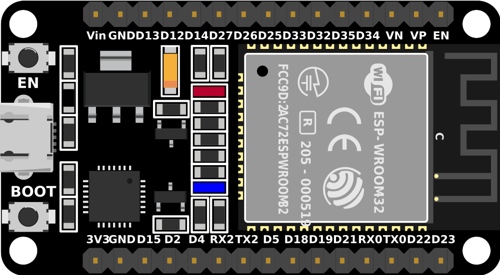
Pin Configuration and Descriptions
The ESP32 (30 pin) has the following pinout:
| Pin Name | Type | Description |
|---|---|---|
| VIN | Power Input | Input voltage (5V) for powering the ESP32 via an external power source. |
| 3V3 | Power Output | Provides 3.3V output for external components. |
| GND | Ground | Ground connection. |
| EN | Enable | Enables or disables the ESP32. Active high. |
| IO0 | GPIO/Boot Mode | General-purpose I/O pin. Used for boot mode selection during programming. |
| IO2 | GPIO | General-purpose I/O pin. |
| IO4 | GPIO | General-purpose I/O pin. |
| IO5 | GPIO | General-purpose I/O pin. |
| IO12 | GPIO/ADC | General-purpose I/O pin with ADC functionality. |
| IO13 | GPIO/ADC | General-purpose I/O pin with ADC functionality. |
| IO14 | GPIO/ADC | General-purpose I/O pin with ADC functionality. |
| IO15 | GPIO/ADC | General-purpose I/O pin with ADC functionality. |
| IO16 | GPIO | General-purpose I/O pin. |
| IO17 | GPIO | General-purpose I/O pin. |
| IO18 | GPIO/SPI | General-purpose I/O pin with SPI functionality. |
| IO19 | GPIO/SPI | General-purpose I/O pin with SPI functionality. |
| IO21 | GPIO/I2C | General-purpose I/O pin with I2C functionality (SDA). |
| IO22 | GPIO/I2C | General-purpose I/O pin with I2C functionality (SCL). |
| IO23 | GPIO/SPI | General-purpose I/O pin with SPI functionality. |
| IO25 | GPIO/DAC | General-purpose I/O pin with DAC functionality. |
| IO26 | GPIO/DAC | General-purpose I/O pin with DAC functionality. |
| IO27 | GPIO/ADC | General-purpose I/O pin with ADC functionality. |
| IO32 | GPIO/ADC | General-purpose I/O pin with ADC functionality. |
| IO33 | GPIO/ADC | General-purpose I/O pin with ADC functionality. |
| IO34 | GPIO/ADC | Input-only pin with ADC functionality. |
| IO35 | GPIO/ADC | Input-only pin with ADC functionality. |
| RXD | UART RX | UART receive pin. |
| TXD | UART TX | UART transmit pin. |
| D0-D8 | GPIO | General-purpose I/O pins. |
Usage Instructions
How to Use the ESP32 in a Circuit
Powering the ESP32:
- Connect the VIN pin to a 5V power source or use the micro-USB port for power and programming.
- Ensure the GND pin is connected to the ground of your circuit.
Programming the ESP32:
- Use the Arduino IDE or ESP-IDF (Espressif IoT Development Framework) for programming.
- Install the ESP32 board package in the Arduino IDE via the Board Manager.
- Connect the ESP32 to your computer using a USB cable and select the appropriate COM port.
Connecting Peripherals:
- Use GPIO pins for digital input/output.
- Use ADC pins for analog input (e.g., sensors).
- Use I2C, SPI, or UART pins for communication with other devices.
Uploading Code:
- Write your code in the Arduino IDE or ESP-IDF.
- Press the "Upload" button in the IDE to flash the code to the ESP32.
- If required, hold the IO0 pin low during the upload process to enter boot mode.
Example Code for Arduino IDE
The following example demonstrates how to blink an LED connected to GPIO2:
// Define the GPIO pin for the LED
#define LED_PIN 2

void setup() {
  pinMode(LED_PIN, OUTPUT); // Set GPIO2 as an output pin
}

void loop() {
  digitalWrite(LED_PIN, HIGH); // Turn the LED on
  delay(1000);                 // Wait for 1 second
  digitalWrite(LED_PIN, LOW);  // Turn the LED off
  delay(1000);                 // Wait for 1 second
}
Important Considerations and Best Practices
- Always use a level shifter when interfacing 5V logic devices with the ESP32's 3.3V GPIO pins.
- Avoid exceeding the maximum current rating of the GPIO pins (12 mA per pin).
- Use decoupling capacitors near the power pins to reduce noise and improve stability.
- For deep sleep applications, ensure proper configuration of wake-up sources.
Troubleshooting and FAQs
Common Issues and Solutions
ESP32 Not Detected by the Computer:
- Ensure the USB cable is functional and supports data transfer.
- Install the correct USB-to-serial driver for your operating system.
Code Upload Fails:
- Check the COM port and board settings in the Arduino IDE.
- Hold the IO0 pin low during the upload process if necessary.
Wi-Fi Connection Issues:
- Verify the SSID and password in your code.
- Ensure the Wi-Fi network is within range and operational.
Random Resets or Instability:
- Check the power supply for sufficient current (at least 500 mA).
- Add decoupling capacitors to stabilize the power supply.
FAQs
Q: Can the ESP32 operate on battery power?
A: Yes, the ESP32 can be powered by a LiPo battery connected to the VIN pin. Use a voltage regulator if necessary.
Q: How do I use the ESP32's Bluetooth functionality?
A: The ESP32 supports both Bluetooth Classic and BLE. Use the BluetoothSerial or BLE libraries in the Arduino IDE to implement Bluetooth features.
Q: What is the maximum number of GPIO pins I can use?
A: The ESP32 (30 pin) provides up to 25 GPIO pins, but some pins may have specific functions or limitations.
Q: Can I use the ESP32 for real-time applications?
A: While the ESP32 is not a real-time processor, its dual-core architecture and RTOS support make it suitable for many real-time tasks.