How to Use Neo 6M GPS Module: Examples, Pinouts, and Specs
Introduction
The Neo 6M GPS module is a compact, high-performance satellite navigation receiver module that provides accurate positioning and navigation information. Utilizing the Global Positioning System (GPS), this module is capable of determining its precise location and time data. It is widely used in various applications such as vehicle tracking systems, asset tracking, personal navigation devices, and in projects that require real-time location-based services.
Explore Projects Built with Neo 6M GPS Module

Explore Projects Built with Neo 6M GPS Module
Common Applications and Use Cases
- Personal and vehicle navigation
- Time synchronization
- Fleet management and asset tracking
- Geocaching and outdoor sports
- UAVs and autonomous vehicles
Technical Specifications
Key Technical Details
- Receiver Type: 50 Channels, GPS L1 frequency, C/A Code
- Sensitivity: Tracking & Navigation: -161 dBm
- Cold starts: -148 dBm
- Time-To-First-Fix: Cold starts: 27s (typ.), Hot starts: 1s (typ.)
- Accuracy: Position: 2.5 m CEP
- Update Rate: 5Hz (default), up to 10 Hz
- Operating Voltage: 3.0V-5.5V
- Operating Current: ~50mA at 5V
- Communication Interface: UART (TTL serial interface)
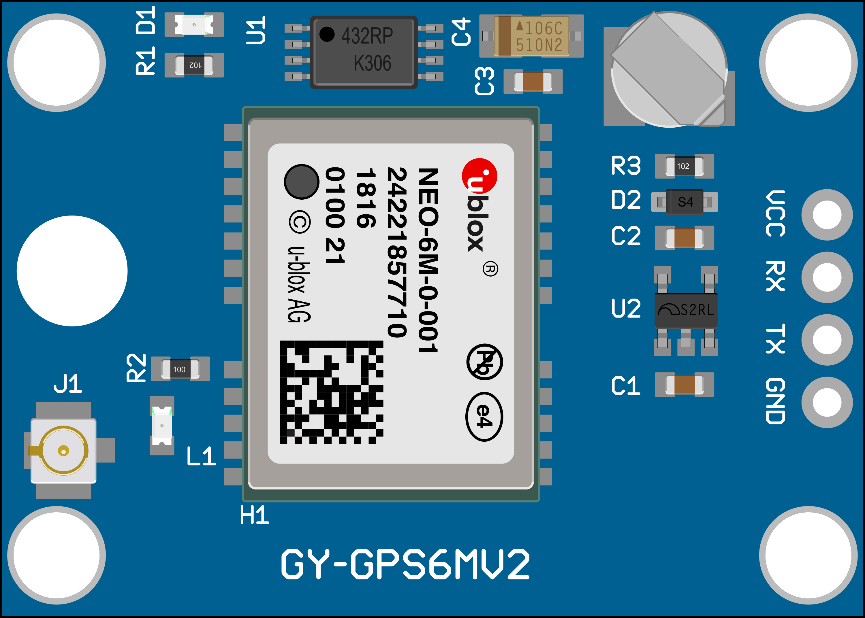
Pin Configuration and Descriptions
| Pin Number | Pin Name | Description |
|---|---|---|
| 1 | VCC | Power supply (3.0V-5.5V input) |
| 2 | GND | Ground |
| 3 | TX | Transmit data (TTL serial output to MCU) |
| 4 | RX | Receive data (TTL serial input from MCU) |
Usage Instructions
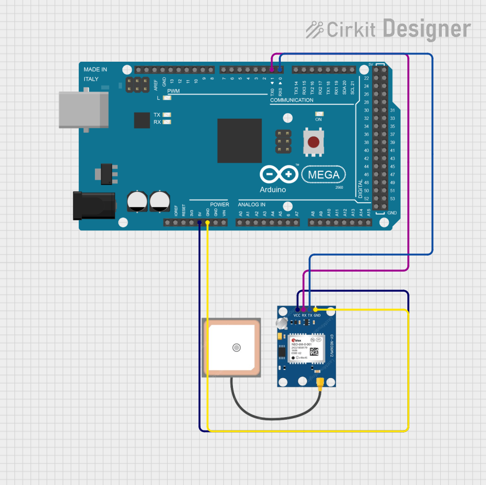
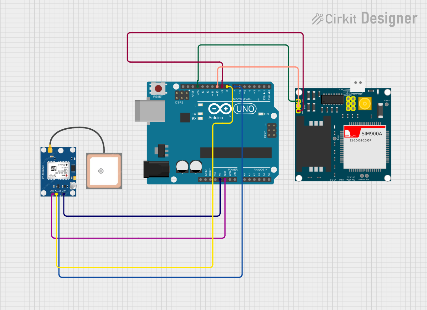
How to Use the Component in a Circuit
- Power Connection: Connect the VCC pin to a 3.0V-5.5V power supply and the GND pin to the ground of your system.
- Data Connection: Connect the TX pin of the GPS module to the RX pin of your microcontroller, and the RX pin of the GPS module to the TX pin of your microcontroller.
- Antenna: Ensure the GPS module's antenna has a clear view of the sky for optimal performance.
Important Considerations and Best Practices
- Power Supply: Ensure that the power supply is stable and within the specified voltage range to avoid damaging the module.
- Serial Communication: Configure your microcontroller's UART interface to match the baud rate of the GPS module (default 9600 bps).
- Signal Acquisition: The initial signal acquisition may take longer, especially in cold starts or in areas with poor satellite visibility. Be patient during this process.
- Interference: Keep the module away from sources of electromagnetic interference for accurate readings.
Example Code for Arduino UNO
#include <SoftwareSerial.h>

// The GPS module's TX pin is connected to Arduino pin 4 (RX)
// The GPS module's RX pin is connected to Arduino pin 3 (TX)
SoftwareSerial gpsSerial(4, 3); // RX, TX

void setup() {
  // Start the serial communication with the host computer
  Serial.begin(9600);
  while (!Serial) {
    ; // Wait for serial port to connect
  }

  // Start the serial communication with the GPS module
  gpsSerial.begin(9600);
  Serial.println("GPS Module Test: Reading NMEA sentences...");
}

void loop() {
  // Check if data is available on the GPS serial
  if (gpsSerial.available()) {
    // Read the data from the GPS module
    char c = gpsSerial.read();
    // Print the data to the host computer's serial monitor
    Serial.write(c);
  }
}
Troubleshooting and FAQs
Common Issues Users Might Face
- No Data Output: Ensure the module's antenna has a clear view of the sky and that the correct baud rate is set.
- Inaccurate Position: Wait for the module to acquire a stable fix; this may take longer during the initial start-up or in areas with poor satellite visibility.
- Intermittent Signal: Avoid placing the module near devices that emit strong electromagnetic interference.
Solutions and Tips for Troubleshooting
- Power Cycle: If the module is unresponsive, try power cycling it by disconnecting and reconnecting the power supply.
- Check Connections: Verify that all connections are secure and that the TX/RX pins are not reversed.
- External Antenna: If signal reception is consistently poor, consider using an external antenna with a clear view of the sky.
FAQs
Q: Can the Neo 6M GPS module work indoors? A: GPS signals are significantly weakened indoors. The module performs best with a clear view of the sky.
Q: What is the default baud rate of the Neo 6M GPS module? A: The default baud rate is 9600 bps.
Q: How can I increase the update rate of the GPS module? A: The update rate can be configured using UBX protocol commands, but this is an advanced topic and requires careful implementation to avoid disrupting the module's operation.
Q: Does the module have a battery backup? A: Some Neo 6M modules come with a battery backup to preserve settings and satellite data, which can reduce the time-to-first-fix on subsequent starts.