
How to Use LM339 (0.1 pin spacing): Examples, Pinouts, and Specs

 Design with LM339 (0.1 pin spacing) in Cirkit Designer
Introduction
The LM339 is a quad comparator IC manufactured by Texas Instruments. It features four independent voltage comparators with open-collector outputs, allowing it to interface with a wide range of logic families. The device is designed for operation from a single power supply or dual supplies, making it versatile for various analog and digital applications.
The 0.1-inch pin spacing ensures compatibility with standard breadboards and PCB layouts, making it easy to prototype and integrate into circuits. The LM339 is widely used in applications such as voltage level detection, signal conditioning, zero-crossing detection, and pulse-width modulation (PWM) circuits.
Explore Projects Built with LM339 (0.1 pin spacing)
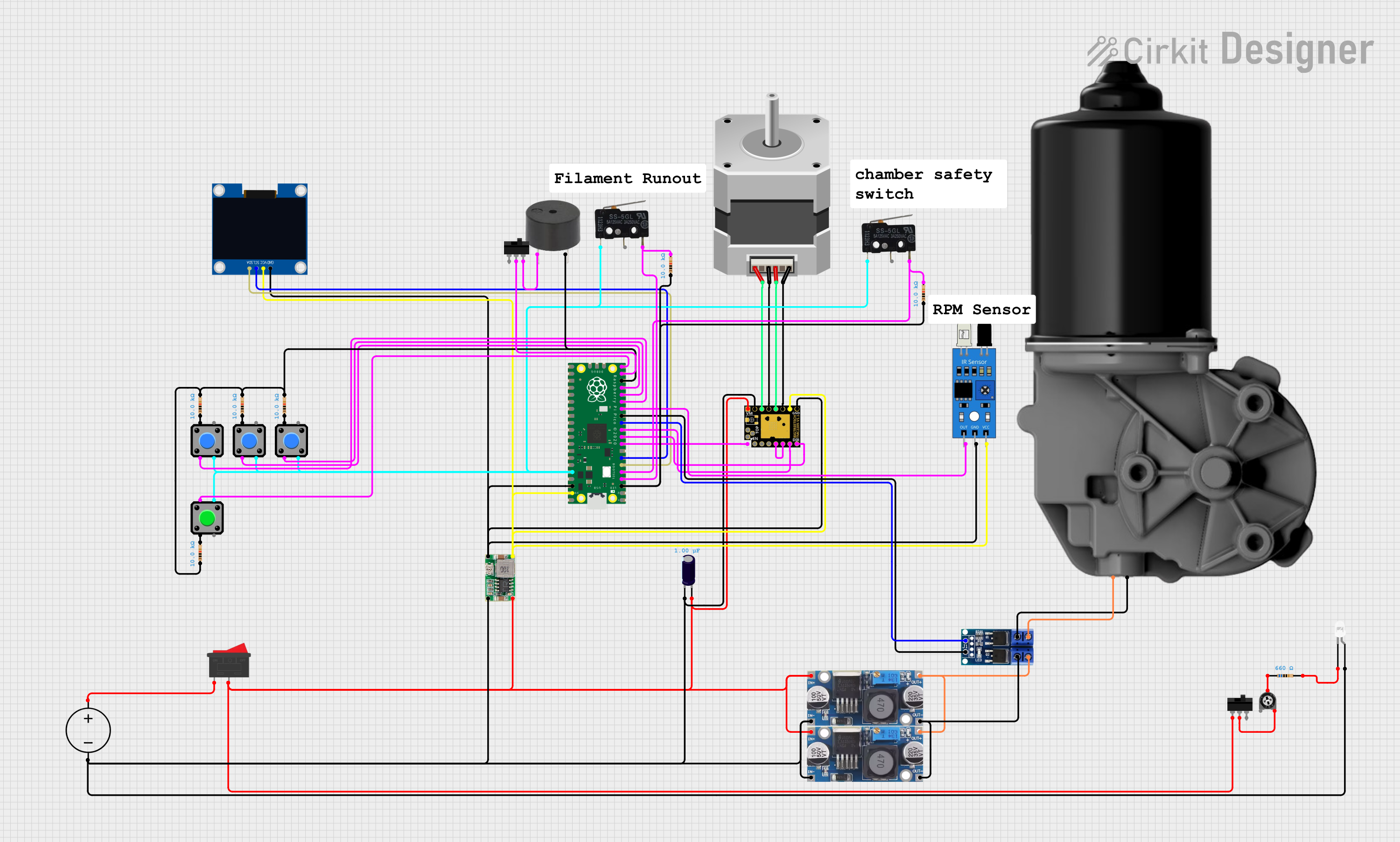 Open Project in Cirkit Designer
 Open Project in Cirkit Designer
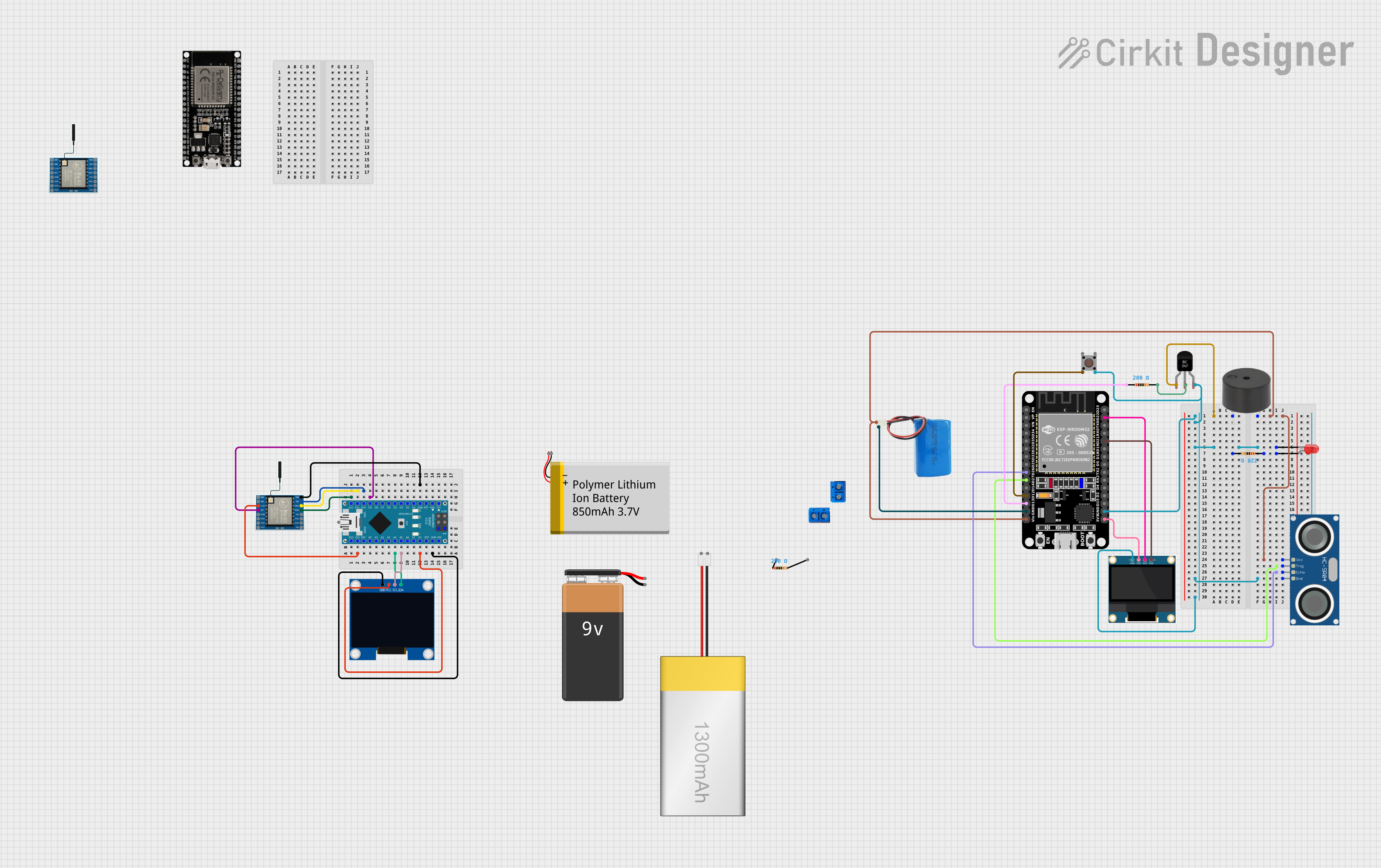 Open Project in Cirkit Designer
 Open Project in Cirkit Designer
Explore Projects Built with LM339 (0.1 pin spacing)
Open Project in Cirkit DesignerOpen Project in Cirkit DesignerOpen Project in Cirkit DesignerOpen Project in Cirkit DesignerCommon Applications
- Voltage level detection (e.g., overvoltage or undervoltage protection)
- Signal conditioning and waveform shaping
- Zero-crossing detection in AC signals
- Pulse-width modulation (PWM) circuits
- Analog-to-digital conversion (ADC) pre-processing
- Oscillator circuits
Technical Specifications
Key Technical Details
| Parameter | Value |
|---|---|
| Manufacturer | Texas Instruments |
| Part Number | LM339 |
| Supply Voltage Range | 2V to 36V (single supply) or ±1V to ±18V (dual supply) |
| Input Offset Voltage | Typically 2mV, maximum 5mV |
| Input Common-Mode Voltage | 0V to (Vcc - 2V) |
| Output Type | Open-collector |
| Output Sink Current | Up to 16mA |
| Operating Temperature Range | -40°C to +85°C |
| Package Type | DIP-14, SOIC-14, TSSOP-14 |
| Pin Spacing | 0.1 inch (2.54 mm) |
Pin Configuration and Descriptions
The LM339 is available in a 14-pin package. The pinout is as follows:
| Pin Number | Pin Name | Description |
|---|---|---|
| 1 | OUTPUT1 | Output of Comparator 1 |
| 2 | INPUT1- | Inverting Input of Comparator 1 |
| 3 | INPUT1+ | Non-Inverting Input of Comparator 1 |
| 4 | VCC- (GND) | Negative Power Supply (Ground) |
| 5 | INPUT2+ | Non-Inverting Input of Comparator 2 |
| 6 | INPUT2- | Inverting Input of Comparator 2 |
| 7 | OUTPUT2 | Output of Comparator 2 |
| 8 | OUTPUT3 | Output of Comparator 3 |
| 9 | INPUT3- | Inverting Input of Comparator 3 |
| 10 | INPUT3+ | Non-Inverting Input of Comparator 3 |
| 11 | VCC+ | Positive Power Supply |
| 12 | INPUT4+ | Non-Inverting Input of Comparator 4 |
| 13 | INPUT4- | Inverting Input of Comparator 4 |
| 14 | OUTPUT4 | Output of Comparator 4 |
Usage Instructions
How to Use the LM339 in a Circuit
- Power Supply: Connect the positive supply voltage (VCC+) to pin 11 and the ground (VCC-) to pin 4. Ensure the supply voltage is within the range of 2V to 36V.
- Inputs: Connect the signal to be compared to the inverting (INPUT-) and non-inverting (INPUT+) pins of the desired comparator. For example, use pins 2 and 3 for Comparator 1.
- Outputs: The outputs (e.g., OUTPUT1 on pin 1) are open-collector, meaning they require a pull-up resistor to function correctly. Connect a resistor (e.g., 10kΩ) between the output pin and the positive supply voltage.
- Reference Voltage: If comparing against a fixed voltage, use a voltage divider or a reference IC to provide the reference voltage to one of the input pins.
- Load: Ensure the output sink current does not exceed 16mA to avoid damaging the IC.
Important Considerations
- The LM339 outputs are open-collector, so they cannot source current. Always use a pull-up resistor.
- The input common-mode voltage range is limited to 0V to (VCC - 2V). Ensure input signals stay within this range.
- Decouple the power supply with a 0.1µF ceramic capacitor close to the IC to reduce noise.
- Avoid leaving unused inputs floating; connect them to ground or VCC.
Example: Using LM339 with Arduino UNO
The following example demonstrates how to use the LM339 to detect a voltage threshold and interface with an Arduino UNO.
Circuit Setup
- Connect VCC+ to 5V and VCC- to GND.
- Use Comparator 1 (pins 1, 2, and 3) to compare an input voltage against a reference voltage (e.g., 2.5V).
- Connect the output (pin 1) to a digital input pin on the Arduino (e.g., pin 2).
- Use a 10kΩ pull-up resistor on the output pin.
Arduino Code
// LM339 Comparator Example with Arduino UNO
// This code reads the output of the LM339 and turns on an LED if the input
// voltage exceeds the reference voltage.

const int comparatorOutputPin = 2; // LM339 output connected to digital pin 2
const int ledPin = 13;             // Onboard LED pin

void setup() {
  pinMode(comparatorOutputPin, INPUT); // Set comparator output as input
  pinMode(ledPin, OUTPUT);             // Set LED pin as output
}

void loop() {
  int comparatorState = digitalRead(comparatorOutputPin); // Read LM339 output

  if (comparatorState == HIGH) {
    digitalWrite(ledPin, HIGH); // Turn on LED if input voltage > reference
  } else {
    digitalWrite(ledPin, LOW);  // Turn off LED otherwise
  }
}
Troubleshooting and FAQs
Common Issues
No Output Signal:
- Ensure a pull-up resistor is connected to the output pin.
- Verify that the input signals are within the common-mode voltage range.
Incorrect Comparisons:
- Check the reference voltage and ensure it is stable.
- Verify that the input signals are connected to the correct pins (inverting and non-inverting).
Excessive Noise:
- Add decoupling capacitors (e.g., 0.1µF) close to the power supply pins.
- Use shielded cables or twisted pairs for input signals in noisy environments.
Output Stuck Low:
- Ensure the pull-up resistor value is appropriate (e.g., 10kΩ).
- Check if the output sink current exceeds 16mA.
FAQs
Q: Can the LM339 be used with a 3.3V power supply?
A: Yes, the LM339 can operate with a supply voltage as low as 2V, making it compatible with 3.3V systems.
Q: Why is a pull-up resistor required on the output?
A: The LM339 has open-collector outputs, which can only sink current. A pull-up resistor is needed to pull the output high when the comparator is not sinking current.
Q: Can I leave unused comparators unconnected?
A: No, unused inputs should be tied to a defined voltage (e.g., ground or VCC) to prevent erratic behavior.
Q: What happens if the input voltage exceeds the supply voltage?
A: Exceeding the input voltage range can damage the IC. Use clamping diodes or resistors to protect the inputs.
This concludes the documentation for the LM339 Quad Comparator.