Cirkit Designer Logo
Cirkit Designer
Your all-in-one circuit design IDE
Home / 
Component Documentation

How to Use SparkFun ESP32 LoRa_1 Channel Gateway: Examples, Pinouts, and Specs

Image of SparkFun ESP32 LoRa_1 Channel Gateway
Cirkit Designer LogoDesign with SparkFun ESP32 LoRa_1 Channel Gateway in Cirkit Designer

Introduction

The SparkFun ESP32 LoRa 1-Channel Gateway is a versatile and powerful electronic component that enables communication between an ESP32 microcontroller and LoRa (Long Range) devices. This gateway is designed to facilitate the creation of LoRa-based wireless networks, which are ideal for IoT (Internet of Things) applications due to their long-range and low-power consumption capabilities. Common applications include remote sensor networks, home automation, and other scenarios where wireless communication over long distances is required.

Explore Projects Built with SparkFun ESP32 LoRa_1 Channel Gateway

Use Cirkit Designer to design, explore, and prototype these projects online. Some projects support real-time simulation. Click "Open Project" to start designing instantly!
ESP32 and LoRa SX1278 Based Wireless Communication Module
Image of Esp 32 as Receiver or Sender: A project utilizing SparkFun ESP32 LoRa_1 Channel Gateway in a practical application
This circuit integrates an ESP32 microcontroller with a LoRa Ra-02 SX1278 module to enable long-range wireless communication. The ESP32 handles the control and data processing, while the LoRa module provides the communication link. The connections include SPI interface and control signals between the ESP32 and the LoRa module, as well as shared power and ground lines.
Cirkit Designer LogoOpen Project in Cirkit Designer
ESP32-Based LoRa Communication Module
Image of Receptor_Proyect_Of_Grade: A project utilizing SparkFun ESP32 LoRa_1 Channel Gateway in a practical application
This circuit integrates an ESP32 microcontroller with a LoRa Ra-02 SX1278 module for long-range wireless communication. The ESP32's digital pins are connected to the LoRa module's SPI interface (MOSI, MISO, SCK, NSS) and control lines (RST, DI00) to enable data transmission and reception. The circuit is likely designed for IoT applications requiring low-power, wide-area network connectivity.
Cirkit Designer LogoOpen Project in Cirkit Designer
ESP32 and LoRa-Based GNSS and IMU Data Logger with Wireless Transmission
Image of Test 0: A project utilizing SparkFun ESP32 LoRa_1 Channel Gateway in a practical application
This circuit consists of two ESP32 microcontrollers, each interfaced with a LoRa Ra-02 SX1278 module for wireless communication. One ESP32 is also connected to an Adafruit BNO055 sensor for orientation data and an L89HA GNSS module for location data, which it transmits via LoRa. The second ESP32 receives this data via LoRa and outputs it to the serial monitor.
Cirkit Designer LogoOpen Project in Cirkit Designer
ESP32-Controlled LoRa Communication Module
Image of receiver: A project utilizing SparkFun ESP32 LoRa_1 Channel Gateway in a practical application
This circuit connects an ESP32 microcontroller to an Adafruit RFM9x LoRa Radio module for wireless communication. The ESP32's GPIO pins are wired to the LoRa module's SPI interface (MOSI, MISO, SCK, CS), interrupt (DIO0), and reset (RST) to enable data transmission and reception over LoRa. The ESP32 also provides power (3V3) and ground (GND) to the LoRa module.
Cirkit Designer LogoOpen Project in Cirkit Designer

Explore Projects Built with SparkFun ESP32 LoRa_1 Channel Gateway

Use Cirkit Designer to design, explore, and prototype these projects online. Some projects support real-time simulation. Click "Open Project" to start designing instantly!
Image of Esp 32 as Receiver or Sender: A project utilizing SparkFun ESP32 LoRa_1 Channel Gateway in a practical application
ESP32 and LoRa SX1278 Based Wireless Communication Module
This circuit integrates an ESP32 microcontroller with a LoRa Ra-02 SX1278 module to enable long-range wireless communication. The ESP32 handles the control and data processing, while the LoRa module provides the communication link. The connections include SPI interface and control signals between the ESP32 and the LoRa module, as well as shared power and ground lines.
Cirkit Designer LogoOpen Project in Cirkit Designer
Image of Receptor_Proyect_Of_Grade: A project utilizing SparkFun ESP32 LoRa_1 Channel Gateway in a practical application
ESP32-Based LoRa Communication Module
This circuit integrates an ESP32 microcontroller with a LoRa Ra-02 SX1278 module for long-range wireless communication. The ESP32's digital pins are connected to the LoRa module's SPI interface (MOSI, MISO, SCK, NSS) and control lines (RST, DI00) to enable data transmission and reception. The circuit is likely designed for IoT applications requiring low-power, wide-area network connectivity.
Cirkit Designer LogoOpen Project in Cirkit Designer
Image of Test 0: A project utilizing SparkFun ESP32 LoRa_1 Channel Gateway in a practical application
ESP32 and LoRa-Based GNSS and IMU Data Logger with Wireless Transmission
This circuit consists of two ESP32 microcontrollers, each interfaced with a LoRa Ra-02 SX1278 module for wireless communication. One ESP32 is also connected to an Adafruit BNO055 sensor for orientation data and an L89HA GNSS module for location data, which it transmits via LoRa. The second ESP32 receives this data via LoRa and outputs it to the serial monitor.
Cirkit Designer LogoOpen Project in Cirkit Designer
Image of receiver: A project utilizing SparkFun ESP32 LoRa_1 Channel Gateway in a practical application
ESP32-Controlled LoRa Communication Module
This circuit connects an ESP32 microcontroller to an Adafruit RFM9x LoRa Radio module for wireless communication. The ESP32's GPIO pins are wired to the LoRa module's SPI interface (MOSI, MISO, SCK, CS), interrupt (DIO0), and reset (RST) to enable data transmission and reception over LoRa. The ESP32 also provides power (3V3) and ground (GND) to the LoRa module.
Cirkit Designer LogoOpen Project in Cirkit Designer

Technical Specifications

Key Technical Details

  • Operating Voltage: 3.3V
  • Frequency Range: 868/915 MHz (region-specific)
  • LoRa Modulation: LoRa and FSK
  • Output Power: Up to +20 dBm
  • Sensitivity: Down to -139 dBm @ SF12, 125 kHz
  • Host Communication: UART, SPI
  • GPIOs: Available for custom applications
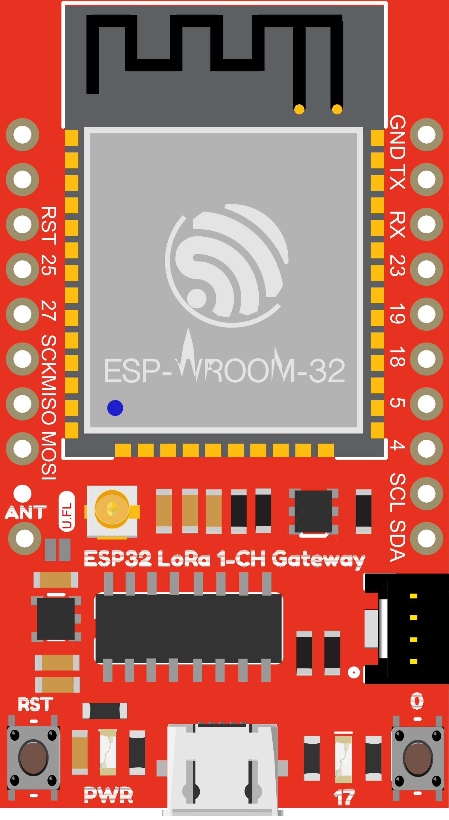
  • Antenna Connector: U.FL and SMA options

Pin Configuration and Descriptions

Pin Number Pin Name Description
1 GND Ground connection
2 3V3 3.3V power supply input
3 TX UART Transmit
4 RX UART Receive
5 RST Reset pin (active low)
6 IO0 General-purpose input/output
7 IO1 General-purpose input/output
8 SCK SPI Clock
9 MISO SPI Master In Slave Out
10 MOSI SPI Master Out Slave In
11 SS SPI Slave Select

Usage Instructions

How to Use the Component in a Circuit

  1. Power Supply: Connect the 3V3 pin to a 3.3V power source and the GND pin to the ground.
  2. Antenna: Attach an appropriate antenna to the U.FL or SMA connector for the frequency band of operation.
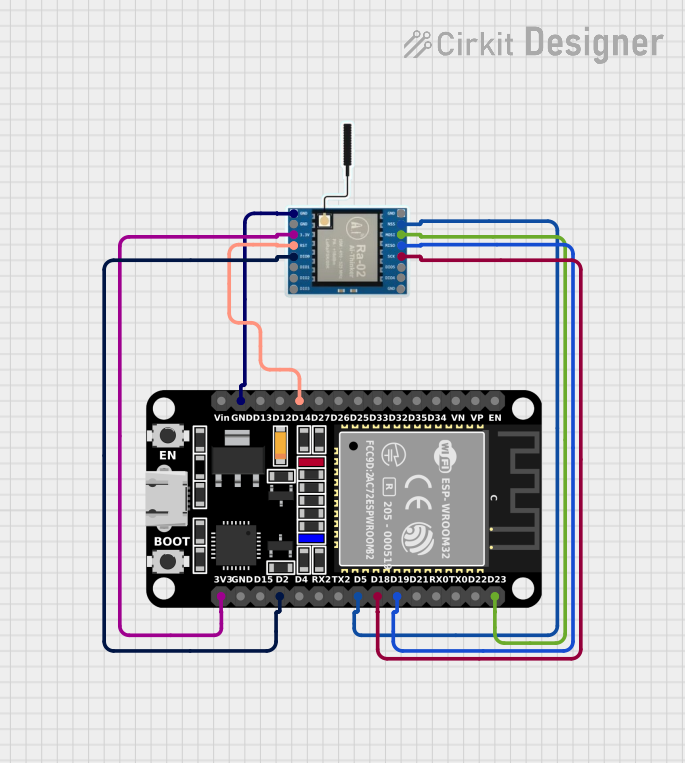
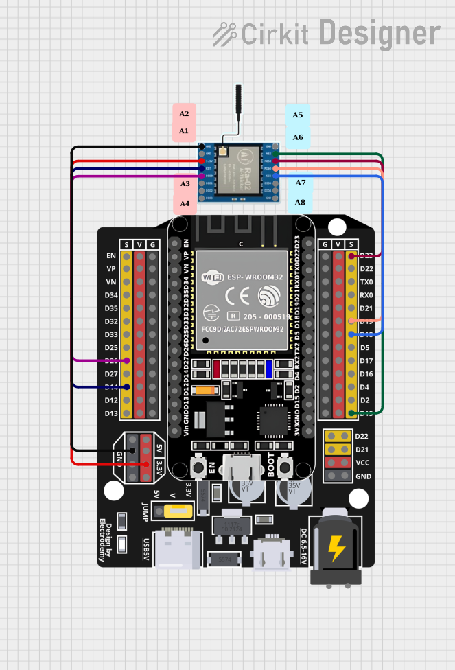
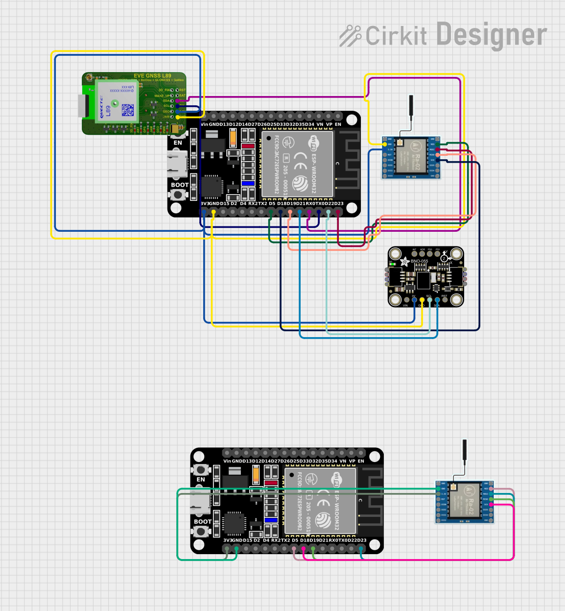
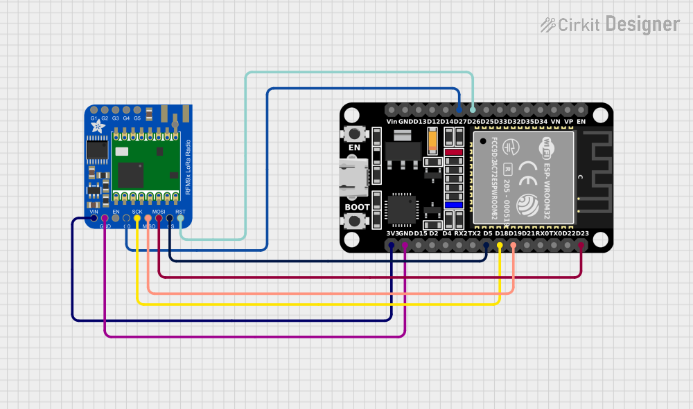
  3. Microcontroller Connection: Use UART or SPI to connect the ESP32 LoRa Gateway to your microcontroller.
  4. Programming: Program the ESP32 to handle LoRa communication using the appropriate libraries.

Important Considerations and Best Practices

  • Ensure that the power supply is stable and clean to avoid damaging the component.
  • Use a proper antenna for the specific frequency band to maximize range and comply with regulations.
  • When using UART, ensure that the baud rates of the ESP32 and the LoRa Gateway match.
  • For SPI communication, ensure that the SPI mode and clock speeds are correctly configured.
  • Follow local regulations regarding the transmission power and frequency usage for LoRa devices.

Troubleshooting and FAQs

Common Issues

  • No Communication: Verify wiring, ensure that the power supply is correct, and check that the UART/SPI settings match.
  • Low Range: Check the antenna connection and orientation, and ensure there are no obstructions in the line of sight.
  • Unexpected Resets: Ensure that the RST pin is not being inadvertently triggered.

Solutions and Tips for Troubleshooting

  • Double-check all connections and solder joints for reliability.
  • Use a logic analyzer or oscilloscope to verify communication signals.
  • Test with a known-good LoRa device to rule out issues with the gateway.

FAQs

Q: Can the ESP32 LoRa Gateway be used with Arduino? A: Yes, it can be interfaced with an Arduino board that supports 3.3V logic levels.

Q: What is the maximum range I can achieve with this gateway? A: The range depends on several factors, including antenna type, environment, and settings, but it can typically reach several kilometers in open areas.

Q: Is this gateway compatible with all LoRa devices? A: It should be compatible with most LoRa devices that operate on the same frequency and follow the LoRaWAN protocol.

Example Code for Arduino UNO

Below is an example code snippet for connecting the SparkFun ESP32 LoRa 1-Channel Gateway to an Arduino UNO. This example assumes you are using a software serial port for communication.

#include <SoftwareSerial.h>

// Define the software serial TX and RX pins
#define RX_PIN 10
#define TX_PIN 11

// Create a software serial object
SoftwareSerial mySerial(RX_PIN, TX_PIN);

void setup() {
  // Start the hardware serial communication
  Serial.begin(9600);
  // Start the software serial communication
  mySerial.begin(9600);
  
  Serial.println("LoRa Gateway Test");
}

void loop() {
  // Check if data is available to read from the LoRa gateway
  if (mySerial.available()) {
    // Read the data and print it to the hardware serial port
    Serial.write(mySerial.read());
  }
  
  // Check if data is available to read from the hardware serial port
  if (Serial.available()) {
    // Read the data and send it to the LoRa gateway
    mySerial.write(Serial.read());
  }
}

Remember to install the SoftwareSerial library if you haven't already, and ensure that the LoRa gateway is correctly configured to communicate at the same baud rate as the software serial port.