How to Use Elegoo Nano V3.0 Board: Examples, Pinouts, and Specs
Introduction
The Elegoo Nano V3.0 Board (Manufacturer Part ID: EL-CB-010) is a compact microcontroller board based on the ATmega328P microcontroller. Designed for ease of use and integration into a wide range of projects, it features USB connectivity for programming and a variety of digital and analog I/O pins. Its small form factor makes it ideal for applications where space is limited, while its compatibility with the Arduino IDE ensures a seamless development experience.
Explore Projects Built with Elegoo Nano V3.0 Board

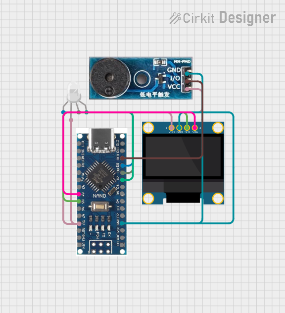

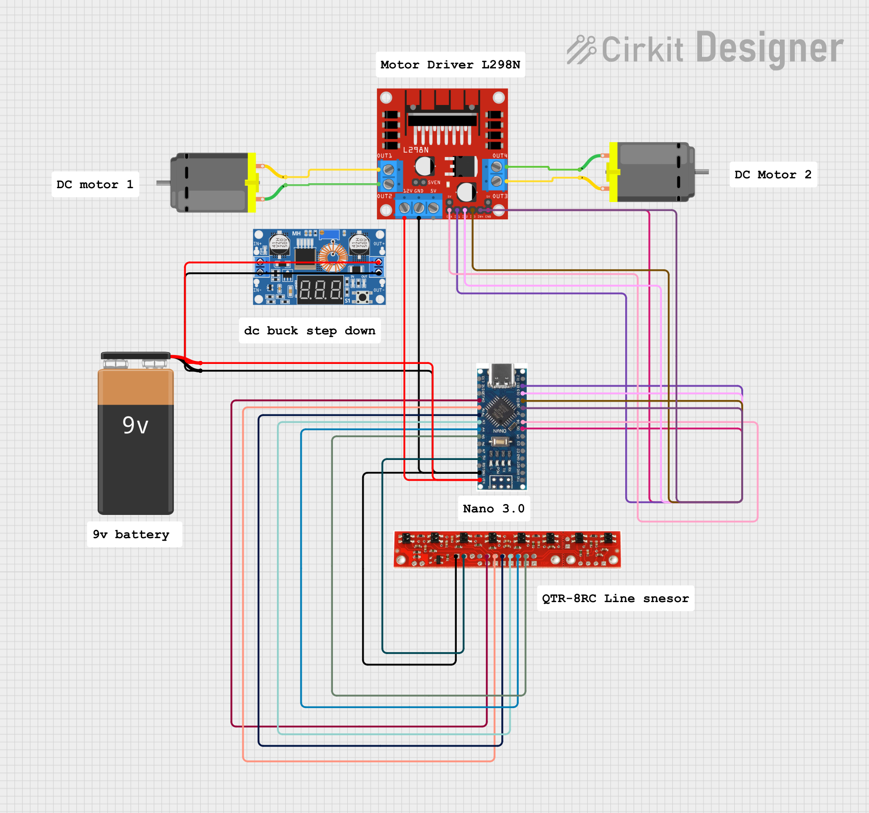
Explore Projects Built with Elegoo Nano V3.0 Board
Common Applications and Use Cases
- Prototyping and development of embedded systems
- Robotics and automation projects
- IoT (Internet of Things) devices
- Sensor data acquisition and processing
- Wearable electronics
- Educational purposes for learning microcontroller programming
Technical Specifications
The Elegoo Nano V3.0 Board is equipped with the following key features and specifications:
| Parameter | Specification |
|---|---|
| Microcontroller | ATmega328P |
| Operating Voltage | 5V |
| Input Voltage (recommended) | 7-12V |
| Input Voltage (limits) | 6-20V |
| Digital I/O Pins | 14 (6 PWM outputs) |
| Analog Input Pins | 8 |
| DC Current per I/O Pin | 40 mA |
| Flash Memory | 32 KB (2 KB used by bootloader) |
| SRAM | 2 KB |
| EEPROM | 1 KB |
| Clock Speed | 16 MHz |
| USB Connectivity | Mini-USB |
| Dimensions | 45 mm x 18 mm |
| Weight | ~7 g |
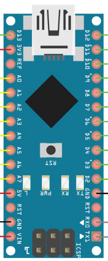
Pin Configuration and Descriptions
The Elegoo Nano V3.0 Board has a total of 30 pins, including power, digital, and analog pins. Below is the pin configuration:
Power Pins
| Pin | Description |
|---|---|
| VIN | Input voltage to the board when using an external power source (7-12V recommended). |
| 5V | Regulated 5V output from the onboard voltage regulator. |
| 3.3V | Regulated 3.3V output (maximum current: 50 mA). |
| GND | Ground pins (multiple GND pins available). |
| RESET | Resets the microcontroller when pulled LOW. |
Digital Pins
| Pin | Description |
|---|---|
| D0-D13 | Digital I/O pins. Pins D3, D5, D6, D9, D10, and D11 support PWM output. |
Analog Pins
| Pin | Description |
|---|---|
| A0-A7 | Analog input pins (10-bit resolution). |
Communication Pins
| Pin | Description |
|---|---|
| TX (D1) | Transmit pin for serial communication. |
| RX (D0) | Receive pin for serial communication. |
| SDA | I2C data line (shared with A4). |
| SCL | I2C clock line (shared with A5). |
Usage Instructions
How to Use the Elegoo Nano V3.0 Board in a Circuit
Powering the Board:
- Connect the board to your computer via the Mini-USB port for programming and power.
- Alternatively, supply power through the VIN pin (7-12V recommended) or the 5V pin (regulated 5V).
Programming the Board:
- Install the Arduino IDE on your computer.
- Select "Arduino Nano" as the board type and "ATmega328P (Old Bootloader)" as the processor in the Arduino IDE.
- Connect the board to your computer using a Mini-USB cable.
- Write your code in the Arduino IDE and upload it to the board.
Connecting Components:
- Use the digital pins (D0-D13) for digital input/output operations.
- Use the analog pins (A0-A7) for reading analog signals (e.g., from sensors).
- Connect external modules (e.g., I2C or SPI devices) to the appropriate communication pins.
Important Considerations and Best Practices
- Ensure the input voltage does not exceed the recommended range to avoid damaging the board.
- Use appropriate resistors when connecting LEDs or other components to the digital pins to limit current.
- Avoid drawing more than 40 mA from any single I/O pin.
- Use the onboard reset button to restart the microcontroller if needed.
Example Code for Arduino UNO-Compatible Projects
The Elegoo Nano V3.0 Board is fully compatible with the Arduino IDE. Below is an example code to blink an LED connected to pin D13:
// Blink an LED connected to pin D13
// This example demonstrates basic digital output functionality.

void setup() {
  pinMode(13, OUTPUT); // Set pin D13 as an output pin
}

void loop() {
  digitalWrite(13, HIGH); // Turn the LED on
  delay(1000);            // Wait for 1 second
  digitalWrite(13, LOW);  // Turn the LED off
  delay(1000);            // Wait for 1 second
}
Troubleshooting and FAQs
Common Issues and Solutions
The board is not recognized by the computer:
- Ensure the correct USB driver is installed. For Windows, install the CH340 driver if required.
- Check the USB cable for damage or try a different cable.
Unable to upload code to the board:
- Verify that the correct board type ("Arduino Nano") and processor ("ATmega328P (Old Bootloader)") are selected in the Arduino IDE.
- Ensure no other program is using the COM port.
- Press the reset button on the board before uploading.
The board is overheating:
- Check the input voltage and ensure it is within the recommended range.
- Avoid drawing excessive current from the I/O pins.
Analog readings are unstable:
- Use proper grounding and shielding for analog sensors.
- Add a capacitor between the sensor's power and ground pins to reduce noise.
FAQs
Q: Can the Elegoo Nano V3.0 Board be powered by batteries?
A: Yes, you can power the board using batteries by connecting them to the VIN pin (7-12V) or the 5V pin (regulated 5V).
Q: Is the Elegoo Nano V3.0 Board compatible with Arduino shields?
A: No, the Nano form factor is not directly compatible with standard Arduino shields. However, you can use a Nano breakout board or custom wiring to connect shields.
Q: How do I reset the board?
A: Press the onboard reset button or connect the RESET pin to GND momentarily.
Q: Can I use the Elegoo Nano V3.0 Board for wireless communication?
A: Yes, you can connect wireless modules (e.g., Bluetooth, Wi-Fi) to the board via the UART, I2C, or SPI interfaces.