How to Use Thermal Overload Relay (TOR): Examples, Pinouts, and Specs
Introduction
A Thermal Overload Relay (TOR) is a protective device designed to safeguard electrical circuits and equipment, such as motors, from damage caused by excessive heat due to overload conditions. It operates by detecting abnormal temperature rises and interrupting the circuit to prevent overheating. TORs are widely used in industrial and commercial applications where motor protection is critical.
Explore Projects Built with Thermal Overload Relay (TOR)


Explore Projects Built with Thermal Overload Relay (TOR)
Common Applications and Use Cases
- Protection of electric motors in industrial machinery
- Safeguarding HVAC systems from overload conditions
- Use in conveyor systems, pumps, and compressors
- Integration into motor control centers (MCCs) for enhanced safety
- Preventing damage to equipment in manufacturing and processing plants
Technical Specifications
Key Technical Details
- Operating Voltage Range: 24V to 690V AC (varies by model)
- Current Rating: 0.1A to 630A (adjustable based on motor requirements)
- Trip Class: Class 10, 20, or 30 (defines the time delay before tripping)
- Temperature Compensation: -20°C to +60°C
- Reset Mode: Manual or automatic
- Contact Configuration: Normally Closed (NC) and Normally Open (NO) auxiliary contacts
- Mounting: Direct mounting on contactors or standalone panel mounting
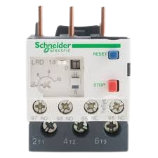
Pin Configuration and Descriptions
Thermal Overload Relays typically have terminals for power connections, auxiliary contacts, and reset functionality. Below is a general pin configuration:
| Pin/Terminal | Description |
|---|---|
| L1, L2, L3 | Input terminals for the three-phase power supply |
| T1, T2, T3 | Output terminals connected to the motor or load |
| 95-96 | Normally Closed (NC) auxiliary contact for signaling or interlocking |
| 97-98 | Normally Open (NO) auxiliary contact for signaling or control |
| Reset Button | Manual reset button to restore operation after a trip |
| Adjustment Dial | Current adjustment dial to set the overload trip current based on motor rating |
Usage Instructions
How to Use the Component in a Circuit
Determine the Motor's Full Load Current (FLC):
- Refer to the motor's nameplate to find its FLC.
- Select a TOR with an adjustable current range that includes the motor's FLC.
Connect the TOR to the Circuit:
- Wire the input terminals (L1, L2, L3) to the power supply.
- Connect the output terminals (T1, T2, T3) to the motor or load.
- Ensure proper tightening of terminal screws to avoid loose connections.
Set the Overload Current:
- Use the adjustment dial to set the trip current slightly above the motor's FLC (e.g., 110% of FLC).
Integrate Auxiliary Contacts:
- Use the NC contact (95-96) for interlocking or stopping the motor in case of a trip.
- Use the NO contact (97-98) for signaling or activating an alarm.
Test the TOR:
- Simulate an overload condition to verify that the relay trips and interrupts the circuit.
- Reset the relay manually or wait for automatic reset (if applicable).
Important Considerations and Best Practices
- Always select a TOR with a current range suitable for the motor's FLC.
- Ensure proper ventilation around the TOR to prevent false tripping due to ambient heat.
- Regularly inspect and test the TOR to ensure reliable operation.
- Avoid setting the trip current too high, as this may fail to protect the motor during overloads.
- For three-phase motors, ensure balanced loading across all phases to prevent nuisance tripping.
Example: Connecting a TOR to an Arduino UNO
While TORs are not typically controlled by microcontrollers like Arduino, you can use the auxiliary contacts for monitoring purposes. Below is an example of how to monitor the NC contact (95-96) with an Arduino UNO:
// Define the pin connected to the TOR's NC auxiliary contact
const int torPin = 2;  // Digital pin 2 on Arduino

void setup() {
  pinMode(torPin, INPUT_PULLUP);  // Set pin as input with internal pull-up resistor
  Serial.begin(9600);            // Initialize serial communication
}

void loop() {
  int torState = digitalRead(torPin);  // Read the state of the TOR's NC contact

  if (torState == HIGH) {
    // If the NC contact is open, the TOR has tripped
    Serial.println("Thermal Overload Relay has tripped!");
  } else {
    // If the NC contact is closed, the TOR is in normal operation
    Serial.println("Thermal Overload Relay is operating normally.");
  }

  delay(1000);  // Wait for 1 second before checking again
}
Troubleshooting and FAQs
Common Issues and Solutions
Issue: TOR trips frequently without apparent overload.
- Solution: Check for loose connections or unbalanced phases. Verify that the trip current is set correctly and that the ambient temperature is within the TOR's operating range.
Issue: TOR does not trip during an overload condition.
- Solution: Ensure the adjustment dial is set to the correct current. Verify that the TOR is functioning properly by testing it with a known overload condition.
Issue: Motor does not start after a trip.
- Solution: Check if the TOR is in manual reset mode. Press the reset button to restore operation. Inspect the auxiliary contacts for proper wiring.
Issue: TOR generates excessive heat during operation.
- Solution: Ensure proper ventilation around the TOR. Verify that the connected load is within the TOR's rated capacity.
FAQs
Q: Can a TOR protect against short circuits?
A: No, a TOR is designed to protect against overload conditions, not short circuits. Use a circuit breaker or fuse for short-circuit protection.Q: How do I select the correct TOR for my motor?
A: Choose a TOR with an adjustable current range that includes the motor's full load current (FLC). Consider the trip class based on the motor's application.Q: Can I use a TOR with single-phase motors?
A: Yes, but ensure the TOR is compatible with single-phase operation and connect only two phases (L1 and L2).Q: What is the difference between manual and automatic reset?
A: In manual reset mode, the TOR requires a physical press of the reset button after a trip. In automatic reset mode, the TOR resets itself after cooling down.
This concludes the documentation for the Thermal Overload Relay (TOR).