How to Use DRV2605L: Examples, Pinouts, and Specs
Introduction
The DRV2605L is a haptic driver IC designed to control vibration motors in various applications. It is widely used in devices requiring tactile feedback, such as smartphones, gaming controllers, wearables, and medical devices. This component simplifies the implementation of haptic feedback by providing built-in waveform libraries and supporting both linear resonant actuators (LRAs) and eccentric rotating mass (ERM) motors. Additionally, the DRV2605L features I2C communication, making it easy to integrate into microcontroller-based systems.
Explore Projects Built with DRV2605L


Explore Projects Built with DRV2605L
Technical Specifications
The DRV2605L is a versatile and efficient haptic driver IC. Below are its key technical specifications:
| Parameter | Value |
|---|---|
| Operating Voltage Range | 2.0V to 5.2V |
| Typical Operating Voltage | 3.3V |
| Maximum Output Voltage | 5.5V |
| Output Drive Type | LRA and ERM motors |
| Communication Interface | I2C |
| Built-in Waveforms | Yes (123 preloaded waveforms) |
| Operating Temperature Range | -40°C to 85°C |
| Package Type | 10-pin VSON (3mm x 3mm) |
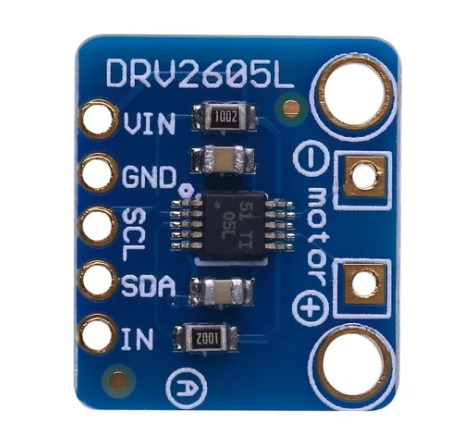
Pin Configuration and Descriptions
The DRV2605L comes in a 10-pin VSON package. Below is the pin configuration:
| Pin Number | Pin Name | Description |
|---|---|---|
| 1 | IN/TRIG | Input trigger pin for external PWM or analog control |
| 2 | SDA | I2C data line |
| 3 | SCL | I2C clock line |
| 4 | VDD | Power supply input (2.0V to 5.2V) |
| 5 | GND | Ground |
| 6 | OUT+ | Positive output for motor connection |
| 7 | OUT- | Negative output for motor connection |
| 8 | EN | Enable pin (active high) |
| 9 | NC | No connection |
| 10 | ASEL | Address select pin for I2C (used to set the I2C address) |
Usage Instructions
How to Use the DRV2605L in a Circuit
- Power Supply: Connect the VDD pin to a 3.3V or 5V power source and the GND pin to ground.
- Motor Connection: Connect the vibration motor (LRA or ERM) to the OUT+ and OUT- pins.
- I2C Communication: Connect the SDA and SCL pins to the corresponding I2C pins on your microcontroller. Use pull-up resistors (typically 4.7kΩ) on the SDA and SCL lines.
- Enable Pin: Pull the EN pin high to enable the device.
- I2C Address: Use the ASEL pin to configure the I2C address if multiple DRV2605L devices are used on the same bus.
Important Considerations and Best Practices
- Ensure the motor type (LRA or ERM) is correctly configured in the DRV2605L's control registers.
- Use decoupling capacitors (e.g., 0.1µF and 1µF) near the VDD pin to stabilize the power supply.
- Avoid exceeding the maximum voltage and current ratings to prevent damage to the IC.
- For optimal performance, match the motor's impedance to the DRV2605L's output specifications.
Example Code for Arduino UNO
Below is an example of how to control the DRV2605L using an Arduino UNO:
#include <Wire.h>
#include <Adafruit_DRV2605.h>

// Create an instance of the DRV2605L library
Adafruit_DRV2605 drv;

void setup() {
  Serial.begin(9600); // Initialize serial communication for debugging
  Serial.println("Initializing DRV2605L...");

  // Initialize the DRV2605L
  if (!drv.begin()) {
    Serial.println("DRV2605L not found. Check connections.");
    while (1); // Halt execution if initialization fails
  }
  Serial.println("DRV2605L initialized successfully.");

  // Select the ERM motor mode
  drv.selectLibrary(1); // Library 1 is optimized for ERM motors
  drv.setMode(DRV2605_MODE_INTTRIG); // Set to internal trigger mode
}

void loop() {
  // Play a haptic effect (e.g., effect #1 from the library)
  drv.setWaveform(0, 1); // Set effect #1 on slot 0
  drv.setWaveform(1, 0); // End of waveform sequence
  drv.go(); // Start playback

  delay(1000); // Wait for 1 second before repeating
}
Notes on the Code
- The
Adafruit_DRV2605library is used for simplicity. Install it via the Arduino Library Manager. - The example demonstrates how to play a preloaded waveform (effect #1) using the internal trigger mode.
Troubleshooting and FAQs
Common Issues
The DRV2605L is not responding to I2C commands.
- Solution: Check the SDA and SCL connections. Ensure pull-up resistors are present and the I2C address matches the configuration.
The motor does not vibrate.
- Solution: Verify the motor connections to the OUT+ and OUT- pins. Ensure the motor type (LRA or ERM) is correctly configured in the control registers.
The device overheats during operation.
- Solution: Ensure the motor's impedance matches the DRV2605L's output specifications. Avoid exceeding the recommended voltage and current ratings.
The Arduino code fails to initialize the DRV2605L.
- Solution: Confirm the DRV2605L is powered correctly and the I2C address is set properly. Use a logic analyzer or oscilloscope to debug I2C communication.
Additional Tips
- Use the DRV2605L's built-in waveform library to simplify haptic feedback implementation.
- For custom haptic effects, refer to the DRV2605L datasheet for details on creating and uploading custom waveforms.
- If using multiple DRV2605L devices on the same I2C bus, configure unique I2C addresses using the ASEL pin.
This concludes the documentation for the DRV2605L. For further details, refer to the official datasheet or application notes.