
How to Use DM542: Examples, Pinouts, and Specs
 Design with DM542 in Cirkit Designer
Introduction
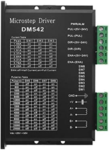
The DM542 is a microstepping driver designed for driving bipolar stepper motors with high precision and smooth motion. Manufactured by Driver, this component supports a wide range of microstepping resolutions, allowing for fine control of motor movement. It is equipped with overcurrent protection and other safety features, making it a reliable choice for industrial automation, CNC machines, 3D printers, and robotics applications.
Explore Projects Built with DM542
 Open Project in Cirkit Designer
 Open Project in Cirkit Designer
 Open Project in Cirkit Designer
 Open Project in Cirkit Designer
Explore Projects Built with DM542
Open Project in Cirkit DesignerOpen Project in Cirkit DesignerOpen Project in Cirkit DesignerOpen Project in Cirkit DesignerCommon Applications
- CNC machines for precise tool positioning
- 3D printers for accurate layer deposition
- Robotics for controlled motion
- Conveyor systems in industrial automation
- Camera sliders and other motion control systems
Technical Specifications
The DM542 offers robust performance and flexibility for various stepper motor applications. Below are its key technical specifications:
| Parameter | Value |
|---|---|
| Supply Voltage Range | 18V to 50V DC |
| Output Current Range | 1.0A to 4.2A (adjustable) |
| Microstepping Resolutions | Full step to 1/128 step |
| Input Signal Voltage | 5V to 24V (logic high) |
| Control Signal Frequency | 0 to 200 kHz |
| Operating Temperature | -10°C to +45°C |
| Protection Features | Overcurrent, overvoltage, and short-circuit protection |
Pin Configuration and Descriptions
The DM542 has several input and output terminals for connecting to the power supply, stepper motor, and control signals. Below is the pin configuration:
Power and Motor Connections
| Pin Name | Description |
|---|---|
| V+ | Positive terminal for DC power supply (18V-50V) |
| V- | Negative terminal for DC power supply (GND) |
| A+ | Positive terminal for motor coil A |
| A- | Negative terminal for motor coil A |
| B+ | Positive terminal for motor coil B |
| B- | Negative terminal for motor coil B |
Control Signal Connections
| Pin Name | Description |
|---|---|
| PUL+ | Positive terminal for pulse signal input |
| PUL- | Negative terminal for pulse signal input |
| DIR+ | Positive terminal for direction signal input |
| DIR- | Negative terminal for direction signal input |
| ENA+ | Positive terminal for enable signal input |
| ENA- | Negative terminal for enable signal input |
Usage Instructions
Connecting the DM542
- Power Supply: Connect a DC power supply (18V-50V) to the V+ and V- terminals. Ensure the power supply can provide sufficient current for the stepper motor.
- Stepper Motor: Connect the stepper motor coils to the A+, A-, B+, and B- terminals. Verify the wiring matches the motor's datasheet.
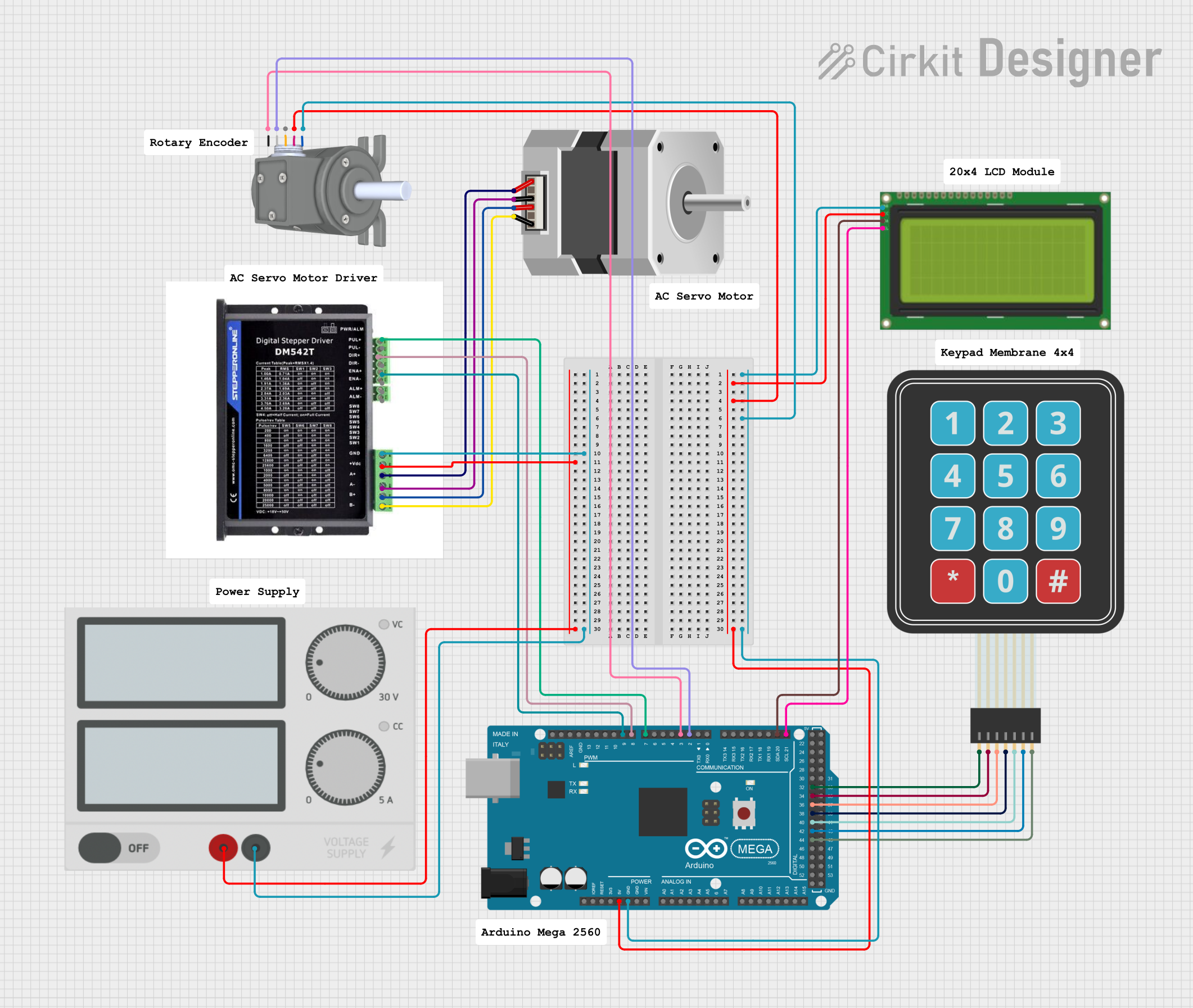
- Control Signals: Connect the PUL+, DIR+, and ENA+ terminals to the control board (e.g., Arduino UNO). Connect the corresponding negative terminals (PUL-, DIR-, ENA-) to the control board's ground.
Configuring Microstepping and Current
- Use the DIP switches on the DM542 to set the desired microstepping resolution and output current. Refer to the DM542 datasheet for the DIP switch settings.
Arduino UNO Example Code
Below is an example of how to control the DM542 using an Arduino UNO:
// Define pins for control signals
const int stepPin = 3;  // Pin connected to PUL+ on DM542
const int dirPin = 4;   // Pin connected to DIR+ on DM542

void setup() {
  pinMode(stepPin, OUTPUT); // Set step pin as output
  pinMode(dirPin, OUTPUT);  // Set direction pin as output

  digitalWrite(dirPin, LOW); // Set initial direction (LOW = one direction)
}

void loop() {
  // Generate step pulses
  digitalWrite(stepPin, HIGH); // Set step pin HIGH
  delayMicroseconds(500);      // Wait for 500 microseconds
  digitalWrite(stepPin, LOW);  // Set step pin LOW
  delayMicroseconds(500);      // Wait for 500 microseconds
}
Important Considerations
- Ensure the power supply voltage is within the specified range (18V-50V).
- Match the motor's current rating with the DM542's output current settings.
- Use shielded cables for control signals to minimize electrical noise.
- Avoid disconnecting the motor while the driver is powered to prevent damage.
Troubleshooting and FAQs
Common Issues and Solutions
Motor Not Moving
- Cause: Incorrect wiring or no pulse signal.
- Solution: Verify motor wiring and ensure the control board is generating pulse signals.
Motor Vibrates but Does Not Rotate
- Cause: Incorrect microstepping or current settings.
- Solution: Check and adjust the DIP switch settings for microstepping and current.
Driver Overheating
- Cause: Insufficient ventilation or excessive current setting.
- Solution: Ensure proper ventilation and reduce the current setting if necessary.
Erratic Motor Movement
- Cause: Electrical noise or unstable power supply.
- Solution: Use shielded cables and a stable power supply.
FAQs
Q: Can the DM542 drive unipolar stepper motors?
A: No, the DM542 is designed for bipolar stepper motors only.
Q: What is the maximum step pulse frequency supported?
A: The DM542 supports a maximum pulse frequency of 200 kHz.
Q: Is it necessary to use the ENA+ and ENA- pins?
A: No, these pins are optional. If not used, leave them disconnected or tied to the appropriate logic level.
Q: Can I use the DM542 with a 12V power supply?
A: No, the minimum supply voltage for the DM542 is 18V. Using a lower voltage may damage the driver or result in improper operation.