
How to Use CT PZEM004T: Examples, Pinouts, and Specs
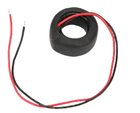
 Design with CT PZEM004T in Cirkit Designer
Introduction
The CT PZEM004T is a multifunctional energy meter designed to measure key electrical parameters such as voltage, current, power, energy, frequency, and power factor. It is commonly used in conjunction with a current transformer (CT) to monitor AC electrical systems. This component is ideal for applications requiring real-time energy monitoring, such as home automation, industrial energy management, and renewable energy systems.
Explore Projects Built with CT PZEM004T
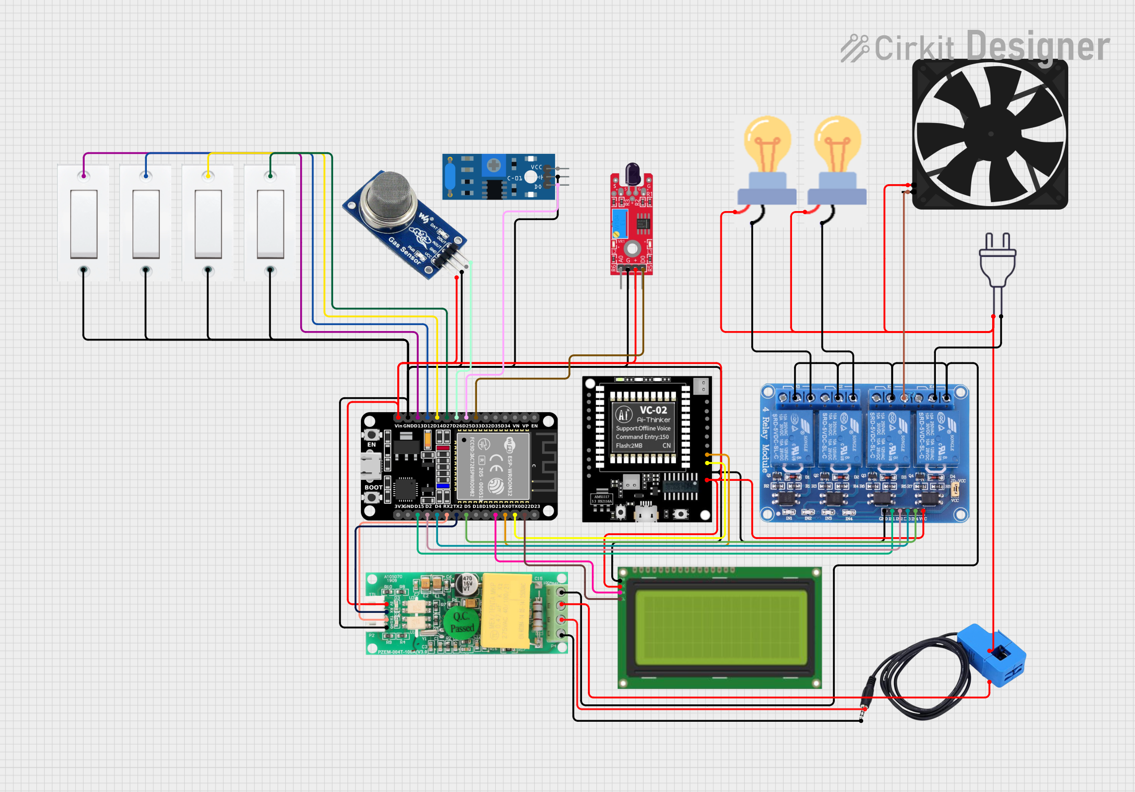 Open Project in Cirkit Designer
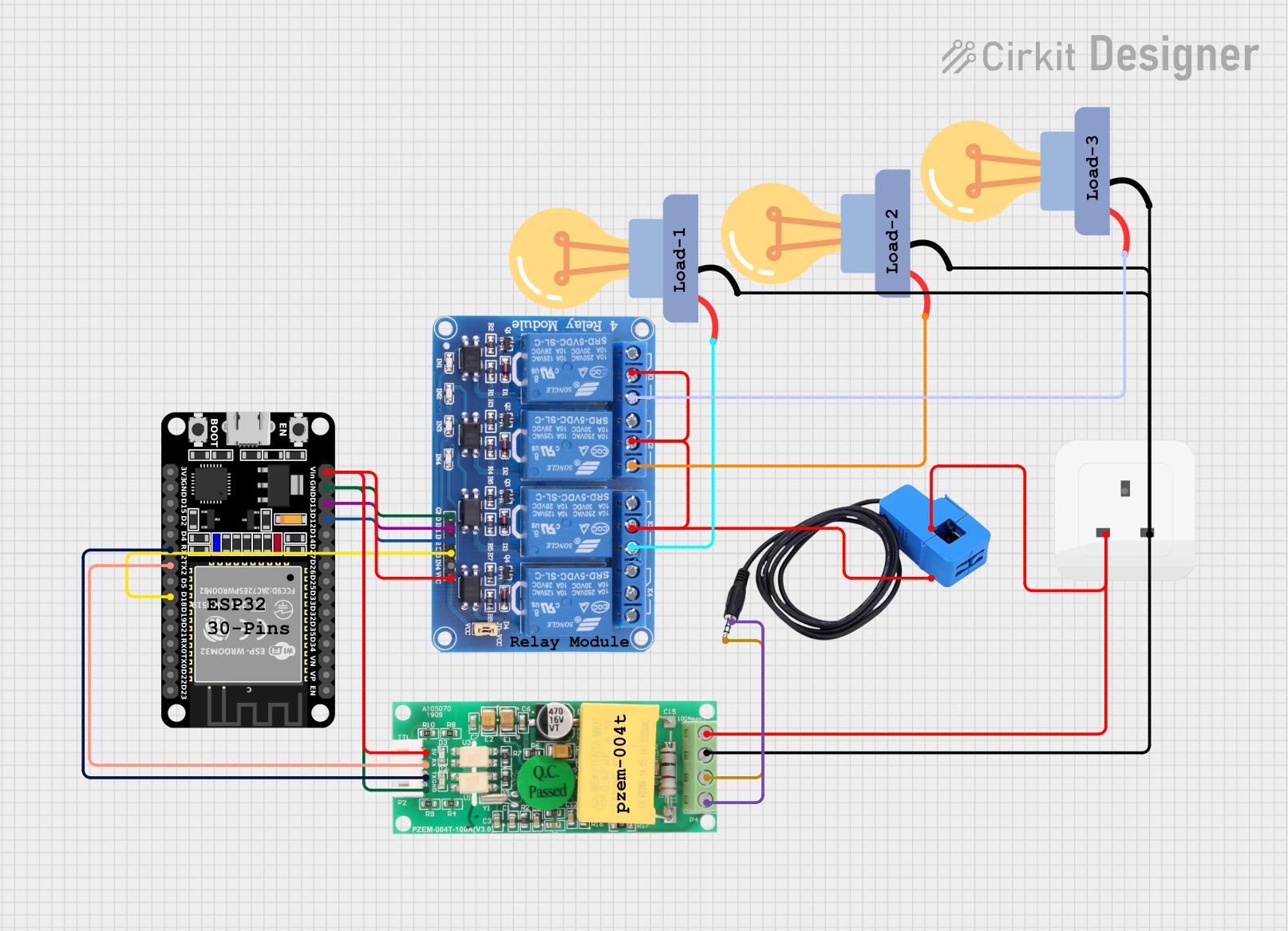 Open Project in Cirkit Designer
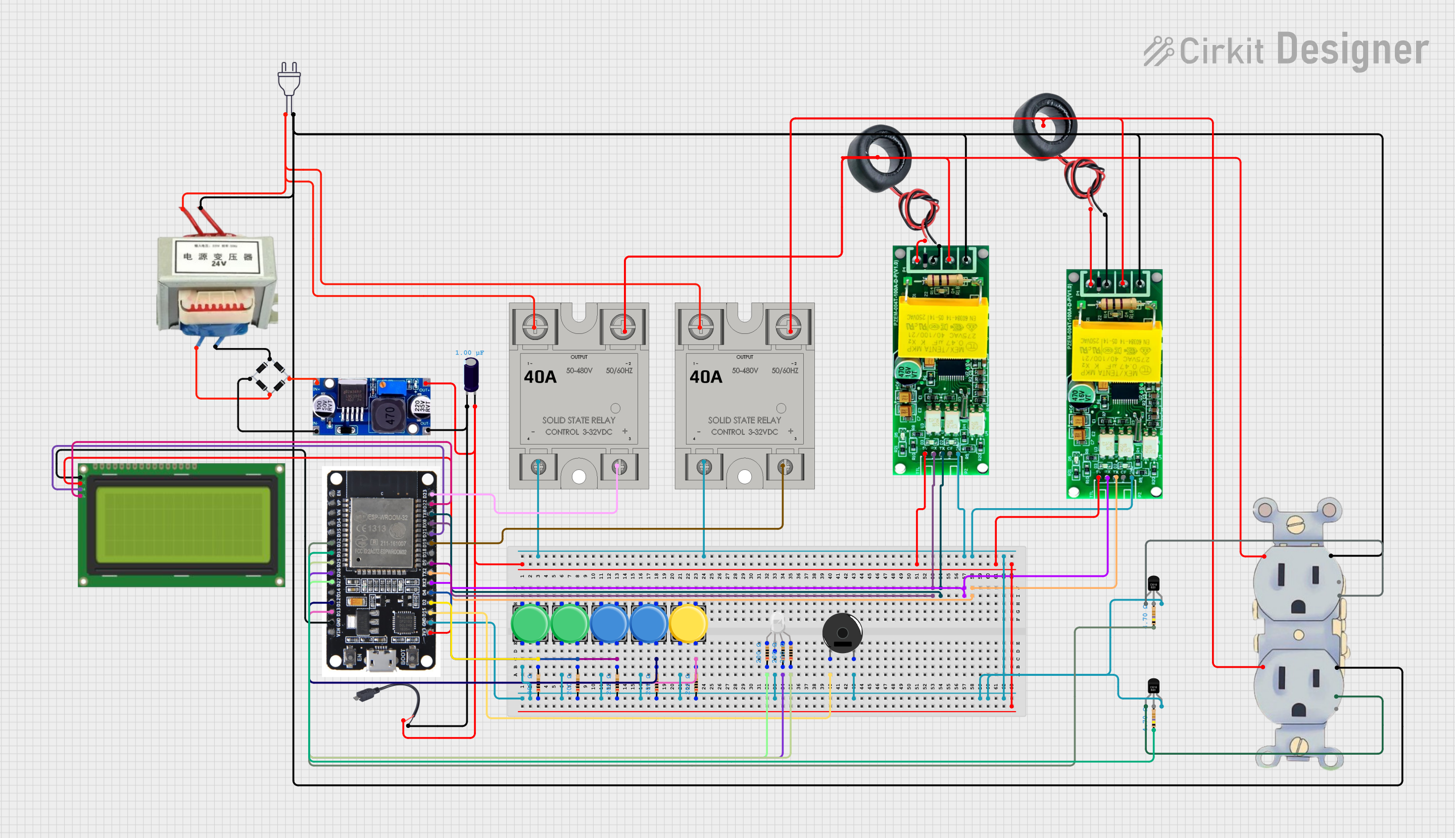 Open Project in Cirkit Designer
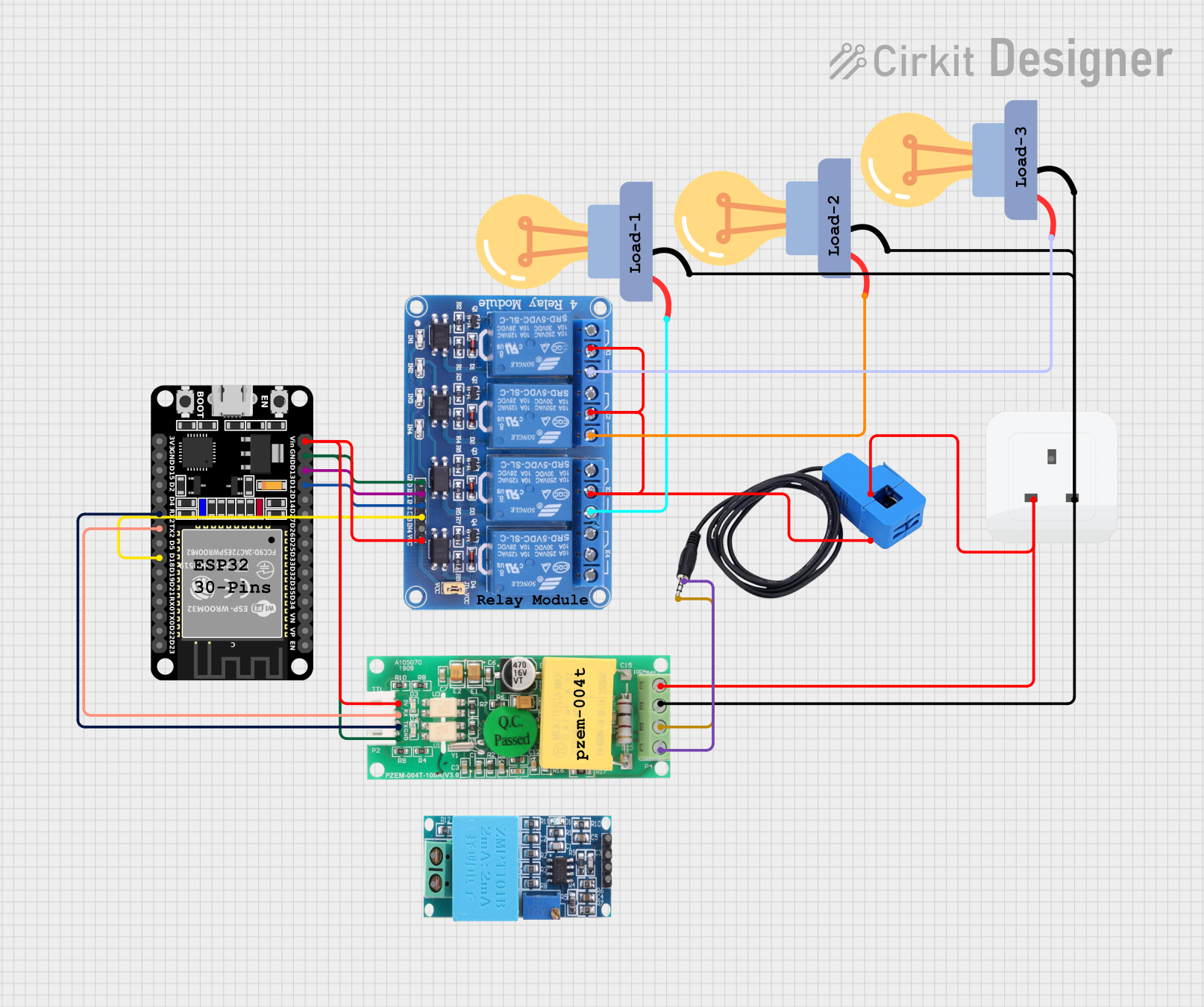 Open Project in Cirkit Designer
Explore Projects Built with CT PZEM004T
Open Project in Cirkit DesignerOpen Project in Cirkit DesignerOpen Project in Cirkit DesignerOpen Project in Cirkit DesignerCommon Applications:
- Home energy monitoring systems
- Industrial equipment energy analysis
- Renewable energy systems (e.g., solar inverters)
- Smart grid and IoT-based energy management
- Power consumption tracking for appliances
Technical Specifications
The CT PZEM004T is a compact and efficient energy meter with the following key specifications:
| Parameter | Specification |
|---|---|
| Voltage Range | 80V - 260V AC |
| Current Range | 0A - 100A (with external CT) |
| Power Range | 0W - 22kW |
| Energy Range | 0kWh - 9999kWh |
| Frequency Range | 45Hz - 65Hz |
| Power Factor Range | 0.00 - 1.00 |
| Communication Protocol | Modbus RTU (RS485) |
| Baud Rate | 9600 bps |
| Operating Temperature | -10°C to 60°C |
| Dimensions | 71mm x 43mm x 25mm |
| Power Consumption | < 1W |
Pin Configuration and Descriptions
The CT PZEM004T module has a simple pinout for easy integration into circuits:
| Pin | Name | Description |
|---|---|---|
| 1 | VCC | Power supply input (5V DC) |
| 2 | GND | Ground connection |
| 3 | TX | UART Transmit pin for data communication |
| 4 | RX | UART Receive pin for data communication |
| 5 | RS485-A | RS485 communication line A |
| 6 | RS485-B | RS485 communication line B |
Usage Instructions
How to Use the CT PZEM004T in a Circuit
- Power Supply: Connect the VCC pin to a 5V DC power source and the GND pin to ground.
- Current Transformer (CT) Connection: Attach the external CT to the AC line you wish to monitor. Ensure the CT is properly oriented to measure current flow.
- Voltage Measurement: Connect the AC voltage input terminals of the PZEM004T to the live and neutral wires of the AC system.
- Communication: Use the TX and RX pins for UART communication or RS485-A and RS485-B for Modbus RTU communication. Ensure proper termination for RS485 lines.
- Data Reading: Use a microcontroller (e.g., Arduino UNO) or a PC with an RS485-to-USB converter to read data from the module.
Important Considerations and Best Practices
- Safety First: Always handle AC connections with care. Ensure the circuit is powered off during installation.
- CT Orientation: The current transformer must be installed in the correct direction to ensure accurate readings.
- Isolation: Use proper electrical isolation when interfacing with high-voltage systems.
- Communication Protocol: Configure the baud rate and Modbus address correctly to avoid communication errors.
- Calibration: Verify the accuracy of the module by comparing its readings with a calibrated energy meter.
Example: Using CT PZEM004T with Arduino UNO
Below is an example Arduino sketch to read data from the CT PZEM004T using UART communication:
#include <SoftwareSerial.h>

// Define RX and TX pins for SoftwareSerial
SoftwareSerial pzemSerial(10, 11); // RX = Pin 10, TX = Pin 11

// Include PZEM004T library (install via Arduino Library Manager)
#include <PZEM004Tv30.h>

// Initialize PZEM004T object
PZEM004Tv30 pzem(&pzemSerial);

void setup() {
  Serial.begin(9600); // Initialize Serial Monitor
  pzemSerial.begin(9600); // Initialize PZEM communication
  Serial.println("PZEM004T Energy Meter Example");
}

void loop() {
  // Read voltage
  float voltage = pzem.voltage();
  if (!isnan(voltage)) {
    Serial.print("Voltage: ");
    Serial.print(voltage);
    Serial.println(" V");
  } else {
    Serial.println("Error reading voltage!");
  }

  // Read current
  float current = pzem.current();
  if (!isnan(current)) {
    Serial.print("Current: ");
    Serial.print(current);
    Serial.println(" A");
  } else {
    Serial.println("Error reading current!");
  }

  // Read power
  float power = pzem.power();
  if (!isnan(power)) {
    Serial.print("Power: ");
    Serial.print(power);
    Serial.println(" W");
  } else {
    Serial.println("Error reading power!");
  }

  // Read energy
  float energy = pzem.energy();
  if (!isnan(energy)) {
    Serial.print("Energy: ");
    Serial.print(energy);
    Serial.println(" kWh");
  } else {
    Serial.println("Error reading energy!");
  }

  // Wait 1 second before next reading
  delay(1000);
}
Troubleshooting and FAQs
Common Issues and Solutions
No Data Output:
- Ensure the module is powered correctly (5V DC to VCC and GND).
- Verify the UART or RS485 connections are secure and correctly configured.
- Check the baud rate (default is 9600 bps) and Modbus address.
Incorrect Readings:
- Verify the CT is installed in the correct orientation.
- Ensure the voltage input terminals are securely connected to the AC system.
- Check for electrical noise or interference in the system.
Communication Errors:
- Ensure proper termination resistors are used for RS485 communication.
- Verify the TX and RX pins are correctly connected to the microcontroller.
FAQs
Q: Can the CT PZEM004T measure DC systems?
A: No, the CT PZEM004T is designed for AC systems only.
Q: What is the maximum current it can measure?
A: The module can measure up to 100A when used with the appropriate current transformer.
Q: Can I use multiple PZEM004T modules in the same system?
A: Yes, but each module must have a unique Modbus address to avoid communication conflicts.
Q: How do I reset the energy counter?
A: The energy counter can be reset via a Modbus command. Refer to the module's datasheet for details.
Q: Is the module compatible with 3-phase systems?
A: The CT PZEM004T is designed for single-phase systems. For 3-phase systems, multiple modules can be used, one for each phase.