Cirkit Designer Logo
Cirkit Designer
Your all-in-one circuit design IDE
Home / 
Component Documentation

How to Use max30100: Examples, Pinouts, and Specs

Image of max30100
Cirkit Designer LogoDesign with max30100 in Cirkit Designer

Introduction

The MAX30100 is an integrated pulse oximetry and heart-rate monitor sensor solution. It combines two LEDs, a photodetector, optimized optics, and low-noise analog signal processing to detect pulse rate and blood oxygen saturation levels (SpO2). This sensor is widely used in wearable health devices, fitness assistants, and medical monitoring devices.

Explore Projects Built with max30100

Use Cirkit Designer to design, explore, and prototype these projects online. Some projects support real-time simulation. Click "Open Project" to start designing instantly!
ESP32-Based Multi-Sensor Health Monitoring System with Bluetooth Connectivity
Image of circuit diagram: A project utilizing max30100 in a practical application
This circuit features an ESP32-WROOM-32UE microcontroller as the central processing unit, interfacing with a variety of sensors and modules. It includes a MAX30100 pulse oximeter and heart-rate sensor, an MLX90614 infrared thermometer, an HC-05 Bluetooth module for wireless communication, and a Neo 6M GPS module for location tracking. All components are powered by a common voltage supply and are connected to specific GPIO pins on the ESP32 for data exchange, with the sensors using I2C communication and the modules using UART.
Cirkit Designer LogoOpen Project in Cirkit Designer
ESP32-Based Health Monitoring System with Bluetooth and GPS
Image of circuit diagram: A project utilizing max30100 in a practical application
This circuit integrates an ESP32 microcontroller with various sensors and modules, including a MAX30100 pulse oximeter, an MLX90614 infrared thermometer, a Neo 6M GPS module, and an HC-05 Bluetooth module. The ESP32 collects data from these sensors and modules via I2C and UART interfaces, enabling wireless communication and GPS tracking capabilities.
Cirkit Designer LogoOpen Project in Cirkit Designer
Battery-Powered Health Monitoring System with Nucleo WB55RG and OLED Display
Image of Pulsefex: A project utilizing max30100 in a practical application
This circuit is a multi-sensor data acquisition system that uses a Nucleo WB55RG microcontroller to interface with a digital temperature sensor (TMP102), a pulse oximeter and heart-rate sensor (MAX30102), and a 0.96" OLED display via I2C. Additionally, it includes a Sim800l module for GSM communication, powered by a 3.7V LiPo battery.
Cirkit Designer LogoOpen Project in Cirkit Designer
ESP32 and MAX30100 Pulse Oximeter
Image of t: A project utilizing max30100 in a practical application
This circuit features an ESP32 microcontroller connected to a MAX30100 sensor, which is likely used for measuring pulse oximetry. The ESP32 is interfaced with the MAX30100 via I2C communication, as indicated by the SDA and SCL connections. Power is supplied to both the ESP32 and the MAX30100 by a 5V battery, with common ground established across the components.
Cirkit Designer LogoOpen Project in Cirkit Designer

Explore Projects Built with max30100

Use Cirkit Designer to design, explore, and prototype these projects online. Some projects support real-time simulation. Click "Open Project" to start designing instantly!
Image of circuit diagram: A project utilizing max30100 in a practical application
ESP32-Based Multi-Sensor Health Monitoring System with Bluetooth Connectivity
This circuit features an ESP32-WROOM-32UE microcontroller as the central processing unit, interfacing with a variety of sensors and modules. It includes a MAX30100 pulse oximeter and heart-rate sensor, an MLX90614 infrared thermometer, an HC-05 Bluetooth module for wireless communication, and a Neo 6M GPS module for location tracking. All components are powered by a common voltage supply and are connected to specific GPIO pins on the ESP32 for data exchange, with the sensors using I2C communication and the modules using UART.
Cirkit Designer LogoOpen Project in Cirkit Designer
Image of circuit diagram: A project utilizing max30100 in a practical application
ESP32-Based Health Monitoring System with Bluetooth and GPS
This circuit integrates an ESP32 microcontroller with various sensors and modules, including a MAX30100 pulse oximeter, an MLX90614 infrared thermometer, a Neo 6M GPS module, and an HC-05 Bluetooth module. The ESP32 collects data from these sensors and modules via I2C and UART interfaces, enabling wireless communication and GPS tracking capabilities.
Cirkit Designer LogoOpen Project in Cirkit Designer
Image of Pulsefex: A project utilizing max30100 in a practical application
Battery-Powered Health Monitoring System with Nucleo WB55RG and OLED Display
This circuit is a multi-sensor data acquisition system that uses a Nucleo WB55RG microcontroller to interface with a digital temperature sensor (TMP102), a pulse oximeter and heart-rate sensor (MAX30102), and a 0.96" OLED display via I2C. Additionally, it includes a Sim800l module for GSM communication, powered by a 3.7V LiPo battery.
Cirkit Designer LogoOpen Project in Cirkit Designer
Image of t: A project utilizing max30100 in a practical application
ESP32 and MAX30100 Pulse Oximeter
This circuit features an ESP32 microcontroller connected to a MAX30100 sensor, which is likely used for measuring pulse oximetry. The ESP32 is interfaced with the MAX30100 via I2C communication, as indicated by the SDA and SCL connections. Power is supplied to both the ESP32 and the MAX30100 by a 5V battery, with common ground established across the components.
Cirkit Designer LogoOpen Project in Cirkit Designer

Common Applications and Use Cases

  • Wearable devices for fitness tracking
  • Medical monitoring equipment
  • Sleep monitoring systems
  • Remote patient monitoring

Technical Specifications

Key Technical Details

  • Operating Voltage: 1.8V to 3.3V
  • LED Peak Wavelength: 660nm (Red), 940nm (IR)
  • Operating Current: 4mA (typical) during LED pulsing
  • Communication Interface: I2C (up to 400kHz)
  • Operating Temperature Range: -40°C to +85°C
  • Resolution: 16-bit ADC for each LED channel

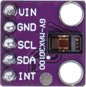
Pin Configuration and Descriptions

Pin Number Name Description
1 VIN Supply voltage (1.8V to 3.3V)
2 SCL I2C clock line
3 SDA I2C data line
4 INT Interrupt pin (active low)
5 RD Red LED cathode
6 IRD IR LED cathode
7 GND Ground

Usage Instructions

How to Use the Component in a Circuit

  1. Power Supply: Connect the VIN pin to a 1.8V to 3.3V power source and GND to the ground.
  2. I2C Communication: Connect SCL and SDA to the I2C clock and data lines, respectively. Ensure pull-up resistors are in place as required for your microcontroller's I2C bus.
  3. Interrupts (Optional): The INT pin can be connected to a digital input on your microcontroller if you wish to use interrupt-driven measurements.

Important Considerations and Best Practices

  • Ensure that the power supply is stable and within the specified voltage range.
  • Avoid exposing the sensor to direct sunlight or strong infrared sources to prevent inaccurate readings.
  • Place the sensor firmly against the skin to get reliable pulse readings.
  • Use proper decoupling capacitors close to the sensor's power supply pins to minimize noise.

Example Code for Arduino UNO

#include <Wire.h>
#include "MAX30100_PulseOximeter.h"

PulseOximeter pox;
uint32_t tsLastReport = 0;

void setup() {
  Serial.begin(115200);
  
  // Initialize the PulseOximeter instance
  if (!pox.begin()) {
    Serial.println("Failed to initialize the pulse oximeter!");
    for(;;);
  } else {
    Serial.println("Pulse oximeter initialized.");
  }
}

void loop() {
  // Make sure to call update as fast as possible
  pox.update();
  if (millis() - tsLastReport > 1000) { // Report every 1 second
    Serial.print("Heart rate:");
    Serial.print(pox.getHeartRate());
    Serial.print("bpm / SpO2:");
    Serial.print(pox.getSpO2());
    Serial.println("%");
    
    tsLastReport = millis();
  }
}

Note: This example assumes the use of a MAX30100 library, such as the one provided by SparkFun or similar. Make sure to install the library through the Arduino IDE before uploading the code.

Troubleshooting and FAQs

Common Issues Users Might Face

  • Inaccurate Readings: Ensure that the sensor is properly placed on the body and that there is no movement that could interfere with the sensor's readings.
  • No Data on I2C: Check the connections and ensure that the correct I2C address is being used. Also, verify that pull-up resistors are installed if they are not built into the microcontroller board.
  • Device Not Powering On: Ensure that the power supply is within the specified range and that all connections are secure.

Solutions and Tips for Troubleshooting

  • Sensor Placement: Make sure the sensor is in direct contact with the skin and that the skin is not too thick.
  • Ambient Light: Shield the sensor from ambient light, as it can interfere with the sensor's ability to accurately measure blood oxygen levels.
  • Check Connections: Revisit all connections, including power and I2C lines, for any loose wires or soldering issues.

FAQs:

  • Q: Can the MAX30100 be used on any part of the body?

    • A: The MAX30100 is typically used on the fingertip or earlobe where the skin is thin enough for the sensor to detect changes in blood color.
  • Q: What is the I2C address of the MAX30100?

    • A: The I2C address for the MAX30100 is 0x57.
  • Q: How can I calibrate the MAX30100?

    • A: The MAX30100 does not require calibration for normal use. However, you can adjust the LED current and sampling rate to optimize performance for specific applications.

This documentation provides an overview of the MAX30100 sensor module, its usage, and troubleshooting tips. For more detailed information, refer to the datasheet provided by the manufacturer.