How to Use jst 1.25_3pin_Female 2 : Examples, Pinouts, and Specs
Introduction
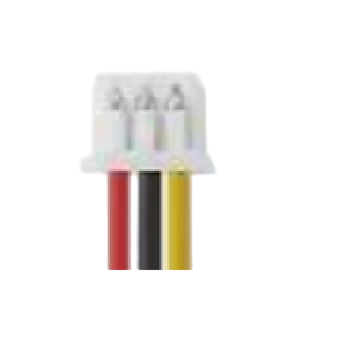
The JST 1.25_3pin_Female connector is a compact, 3-pin female connector with a 1.25mm pitch. It is widely used in electronic applications where secure and reliable electrical connections are required in a small form factor. This connector is ideal for use in compact devices, such as drones, wearables, and other portable electronics, due to its small size and lightweight design.
Explore Projects Built with jst 1.25_3pin_Female 2


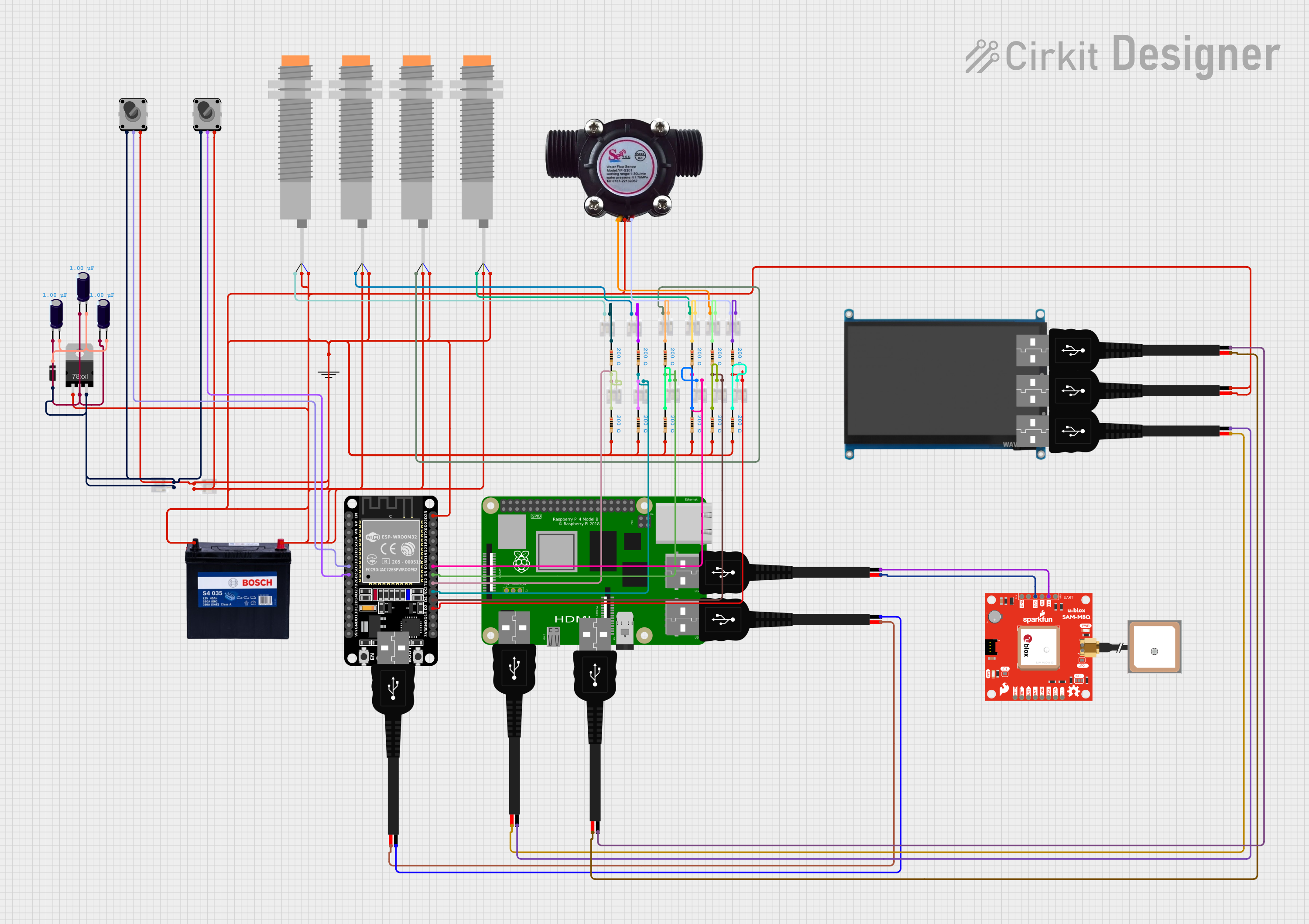

Explore Projects Built with jst 1.25_3pin_Female 2
Common Applications and Use Cases
- Connecting sensors, modules, or peripherals in compact electronic devices
- Power delivery and signal transmission in drones and robotics
- Wearable technology and IoT devices
- Battery connections in small-scale projects
- Prototyping and development of compact circuits
Technical Specifications
The following table outlines the key technical details of the JST 1.25_3pin_Female connector:
| Parameter | Value |
|---|---|
| Connector Type | Female |
| Number of Pins | 3 |
| Pitch (Pin Spacing) | 1.25mm |
| Current Rating | 1A (maximum) |
| Voltage Rating | 50V (maximum) |
| Wire Gauge Supported | 28-32 AWG |
| Material | Plastic housing, metal pins |
| Operating Temperature | -25°C to +85°C |
Pin Configuration and Descriptions
The JST 1.25_3pin_Female connector has three pins, typically used for power, ground, and signal connections. The pinout is as follows:
| Pin Number | Label | Description |
|---|---|---|
| 1 | VCC | Power supply (positive voltage) |
| 2 | GND | Ground (0V reference) |
| 3 | Signal | Data or control signal |
Note: The pinout may vary depending on the specific application or device. Always refer to the datasheet or circuit diagram for your project.
Usage Instructions
How to Use the JST 1.25_3pin_Female Connector in a Circuit
Prepare the Wires:
- Use wires with a gauge of 28-32 AWG for compatibility.
- Strip approximately 2-3mm of insulation from the ends of the wires.
Crimp the Contacts:
- Use a compatible crimping tool to attach the metal contacts to the stripped wire ends.
- Ensure a secure crimp to avoid loose connections.
Insert the Contacts:
- Insert the crimped contacts into the connector housing until they click into place.
- Verify that the contacts are fully seated and aligned with the housing.
Connect to the Circuit:
- Plug the JST 1.25_3pin_Female connector into the corresponding male connector on your device or circuit board.
- Ensure proper alignment to avoid damaging the pins.
Secure the Connection:
- If necessary, use additional securing mechanisms (e.g., adhesive or cable ties) to prevent accidental disconnection.
Important Considerations and Best Practices
- Polarity: Double-check the pinout and polarity before connecting the connector to avoid damage to your circuit.
- Current and Voltage Limits: Do not exceed the rated current (1A) or voltage (50V) to ensure safe operation.
- Crimping Tool: Use a high-quality crimping tool designed for JST connectors to achieve reliable connections.
- Environmental Conditions: Avoid exposing the connector to extreme temperatures or moisture, as this may degrade performance.
Example: Connecting to an Arduino UNO
The JST 1.25_3pin_Female connector can be used to connect a sensor or module to an Arduino UNO. Below is an example of how to connect a sensor with a JST 1.25_3pin_Female connector to the Arduino:
Wiring:
- Pin 1 (VCC) → Arduino 5V
- Pin 2 (GND) → Arduino GND
- Pin 3 (Signal) → Arduino digital pin (e.g., D2)
Sample Code:
// Example code for reading a digital signal from a sensor connected via
// a JST 1.25_3pin_Female connector to an Arduino UNO.

const int signalPin = 2; // Pin connected to the Signal pin of the sensor
int sensorValue = 0;     // Variable to store the sensor reading

void setup() {
  pinMode(signalPin, INPUT); // Set the signal pin as an input
  Serial.begin(9600);        // Initialize serial communication
}

void loop() {
  sensorValue = digitalRead(signalPin); // Read the digital signal
  Serial.print("Sensor Value: ");
  Serial.println(sensorValue);         // Print the sensor value to the Serial Monitor
  delay(500);                          // Wait for 500ms before the next reading
}
Note: Ensure the sensor or module connected to the JST 1.25_3pin_Female connector is compatible with the Arduino's voltage levels.
Troubleshooting and FAQs
Common Issues and Solutions
Loose Connections:
- Issue: The connector feels loose or disconnects easily.
- Solution: Ensure the crimped contacts are fully inserted into the housing. Use a compatible male connector for a secure fit.
Incorrect Pinout:
- Issue: The circuit does not work as expected.
- Solution: Verify the pinout and ensure the connections match the circuit diagram.
Overheating:
- Issue: The connector becomes hot during operation.
- Solution: Check that the current and voltage do not exceed the rated limits (1A, 50V).
Damaged Contacts:
- Issue: The metal contacts are bent or broken.
- Solution: Replace the damaged contacts and ensure proper crimping.
FAQs
Q1: Can I use the JST 1.25_3pin_Female connector for high-power applications?
A1: No, this connector is designed for low-power applications with a maximum current rating of 1A and voltage rating of 50V.
Q2: What crimping tool should I use for this connector?
A2: Use a crimping tool specifically designed for JST 1.25mm pitch connectors to ensure reliable connections.
Q3: Can I solder wires directly to the connector?
A3: While possible, soldering is not recommended as it may damage the plastic housing. Crimping is the preferred method.
Q4: Is this connector compatible with other JST series connectors?
A4: No, the JST 1.25_3pin_Female connector is only compatible with male connectors of the same series and pitch (1.25mm).