Cirkit Designer
Your all-in-one circuit design IDE
Home /
Component Documentation
How to Use PZEM-017: Examples, Pinouts, and Specs

Introduction
The PZEM-017 is a digital multi-meter manufactured by PeaceFair, designed to measure voltage, current, power, and energy consumption in electrical circuits. This versatile component is widely used in monitoring systems for renewable energy sources, industrial machinery, home energy management, and other applications where precise electrical measurements are crucial.
Explore Projects Built with PZEM-017
ESP32-Based Smart Environmental Monitoring System with Relay Control

This is a smart environmental monitoring and control system featuring an ESP32 microcontroller interfaced with a PZEM004T for power monitoring, relay modules for actuating bulbs and a fan, and an LCD for user interface. It includes flame, gas, and vibration sensors for safety monitoring purposes.
ESP32-Controlled AC Lighting System with Power Monitoring

This circuit features an ESP32 microcontroller interfaced with a PZEM004T power monitoring module and a 4-channel relay module controlling multiple AC LED bulbs. The ESP32 uses GPIO pins to control the relays, which in turn switch the LED bulbs on and off. The PZEM004T is connected to the ESP32 for communication and to a current sensor for monitoring power consumption of the connected load through the relay contacts.
ESP32-Based Smart Energy Monitoring and Control System with PZEM004t and LCD Display
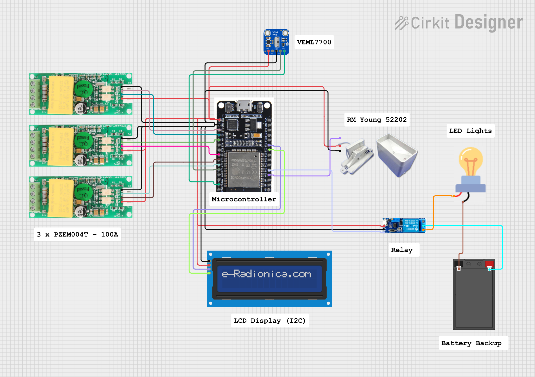
This circuit is a monitoring and control system using an ESP32 microcontroller. It integrates multiple PZEM004t energy meters, a rain gauge, a light sensor, and an LCD display for data visualization. Additionally, it controls a relay module to switch a bulb on or off based on sensor inputs.
ESP32-Based Smart Power Monitoring and Control System with Wi-Fi Connectivity

This circuit is a smart power monitoring and control system using an ESP32 microcontroller. It features multiple sensors and components, including PZEM-004T AC modules for voltage and current measurement, DS18B20 temperature sensors, an LCD for display, and solid-state relays for controlling power outlets. The system is integrated with Blynk for remote monitoring and control, and includes pushbuttons for local interaction.
Explore Projects Built with PZEM-017
ESP32-Based Smart Environmental Monitoring System with Relay Control
This is a smart environmental monitoring and control system featuring an ESP32 microcontroller interfaced with a PZEM004T for power monitoring, relay modules for actuating bulbs and a fan, and an LCD for user interface. It includes flame, gas, and vibration sensors for safety monitoring purposes.
ESP32-Controlled AC Lighting System with Power Monitoring
This circuit features an ESP32 microcontroller interfaced with a PZEM004T power monitoring module and a 4-channel relay module controlling multiple AC LED bulbs. The ESP32 uses GPIO pins to control the relays, which in turn switch the LED bulbs on and off. The PZEM004T is connected to the ESP32 for communication and to a current sensor for monitoring power consumption of the connected load through the relay contacts.
ESP32-Based Smart Energy Monitoring and Control System with PZEM004t and LCD Display
This circuit is a monitoring and control system using an ESP32 microcontroller. It integrates multiple PZEM004t energy meters, a rain gauge, a light sensor, and an LCD display for data visualization. Additionally, it controls a relay module to switch a bulb on or off based on sensor inputs.
ESP32-Based Smart Power Monitoring and Control System with Wi-Fi Connectivity
This circuit is a smart power monitoring and control system using an ESP32 microcontroller. It features multiple sensors and components, including PZEM-004T AC modules for voltage and current measurement, DS18B20 temperature sensors, an LCD for display, and solid-state relays for controlling power outlets. The system is integrated with Blynk for remote monitoring and control, and includes pushbuttons for local interaction.
Technical Specifications
Key Technical Details
- Voltage Measurement Range: 0 - 300V
- Current Measurement Range: 0 - 100A (requires external shunt)
- Power Measurement Range: 0 - 30,000W
- Energy Measurement Range: 0 - 99999kWh
- Measurement Accuracy: ±1.0%
- Operating Temperature: -10°C to 60°C
- Frequency Detection: 45Hz - 65Hz
Pin Configuration and Descriptions
| Pin Number | Function | Description |
|---|---|---|
| 1 | V+ | Positive voltage input for power supply (DC 7-12V) |
| 2 | V- | Negative voltage input for power supply |
| 3 | RS485 A | RS485 communication line A (non-inverting) |
| 4 | RS485 B | RS485 communication line B (inverting) |
| 5 | NC | No connection |
| 6 | IN+ | Positive input for voltage measurement |
| 7 | IN- | Negative input for voltage measurement |
| 8 | Shunt+ | Connection to the positive side of the external shunt |
| 9 | Shunt- | Connection to the negative side of the external shunt |
Usage Instructions
How to Use the PZEM-017 in a Circuit
- Power Supply: Connect a DC 7-12V power source to the V+ and V- pins.
- Voltage Measurement: Connect the circuit's voltage to be measured across the IN+ and IN- pins.
- Current Measurement: Connect the external shunt across the Shunt+ and Shunt- pins. The load should pass through the shunt.
- Communication: Use the RS485 A and B lines to communicate with the PZEM-017 using a compatible RS485 to TTL converter.
Important Considerations and Best Practices
- Ensure that the power supply voltage does not exceed the specified range.
- Do not exceed the voltage and current measurement ranges to avoid damaging the device.
- Use twisted pair cables for RS485 communication to reduce electromagnetic interference.
- Always disconnect the power before making or changing connections to the PZEM-017.
Troubleshooting and FAQs
Common Issues
- No Data on RS485: Check the connections and ensure that the correct baud rate and data format are used (9600 bps, 8N1).
- Inaccurate Readings: Verify that the connections are secure and that the external shunt is properly rated for the current being measured.
Solutions and Tips for Troubleshooting
- Double-check wiring connections according to the pin configuration.
- Ensure that the power supply is stable and within the specified voltage range.
- Use a calibrated multimeter to verify the accuracy of the PZEM-017 readings.
Arduino UNO Example Code
#include <ModbusMaster.h>

// Instantiate ModbusMaster object
ModbusMaster node;

void setup() {
  // Initialize Modbus communication baud rate
  Serial.begin(9600);

  // Set slave ID of the PZEM-017
  node.begin(1, Serial);
}

void loop() {
  uint8_t result;

  // Read 10 registers starting at 0x0000 (Voltage, Current, Power, etc.)
  result = node.readInputRegisters(0x0000, 10);

  if (result == node.ku8MBSuccess) {
    // Process the received data
    float voltage = node.getResponseBuffer(0x0000) / 10.0;
    float current = node.getResponseBuffer(0x0001) / 100.0;
    // Add additional processing for power and energy

    // Print the measured voltage and current
    Serial.print("Voltage: ");
    Serial.print(voltage);
    Serial.println(" V");

    Serial.print("Current: ");
    Serial.print(current);
    Serial.println(" A");
  }

  // Wait for a short period before reading again
  delay(1000);
}
Note: This example assumes the use of a RS485 to TTL converter connected to the Arduino's serial pins. The ModbusMaster library is used for Modbus RTU communication. Ensure that the library is installed in your Arduino IDE before uploading the code to the Arduino UNO.
Remember to adhere to the 80 character line length limit for code comments, wrapping text as necessary.