How to Use Optocoupler: Examples, Pinouts, and Specs
Introduction
An optocoupler, also known as an optoisolator, is an electronic component that transfers electrical signals between two isolated circuits using light waves. It provides electrical isolation between its input and output, ensuring that high-voltage or noisy signals do not interfere with sensitive low-voltage circuits. Optocouplers are widely used in applications where signal integrity and safety are critical.
Explore Projects Built with Optocoupler


Explore Projects Built with Optocoupler
Common Applications and Use Cases
- Isolating microcontrollers or digital circuits from high-voltage systems
- Protecting sensitive components from voltage spikes or surges
- Signal transmission in noisy environments
- Switching power supplies and motor control circuits
- Communication between systems with different ground potentials
Technical Specifications
Below are the key technical details for the AC Optocoupler:
General Specifications
| Parameter | Value |
|---|---|
| Manufacturer | AC |
| Part ID | Optocoupler |
| Isolation Voltage | 5,000 V (typical) |
| Input Forward Voltage | 1.2 V (typical) |
| Input Current | 10 mA to 20 mA (typical) |
| Output Voltage | Up to 35 V |
| Output Current | 50 mA (maximum) |
| Response Time | 2 µs to 5 µs (typical) |
| Operating Temperature | -40°C to +85°C |
Pin Configuration and Descriptions
The optocoupler typically comes in a 4-pin or 6-pin DIP (Dual Inline Package). Below is the pin configuration for a standard 4-pin optocoupler:
| Pin Number | Name | Description |
|---|---|---|
| 1 | Anode (A) | Positive terminal of the LED (input side) |
| 2 | Cathode (K) | Negative terminal of the LED (input side) |
| 3 | Emitter (E) | Emitter of the phototransistor (output side) |
| 4 | Collector (C) | Collector of the phototransistor (output side) |
For a 6-pin optocoupler, additional pins may include a base pin for the phototransistor or NC (No Connection) pins.
Usage Instructions
How to Use the Optocoupler in a Circuit
Input Side (LED):
- Connect the anode (Pin 1) to the positive side of the input signal through a current-limiting resistor.
- Connect the cathode (Pin 2) to the ground of the input circuit.
- Calculate the resistor value using Ohm's law:
( R = \frac{V_{in} - V_f}{I_f} ),
where ( V_{in} ) is the input voltage, ( V_f ) is the forward voltage of the LED (1.2 V typical), and ( I_f ) is the desired forward current (e.g., 10 mA).
Output Side (Phototransistor):
- Connect the collector (Pin 4) to the positive supply voltage of the output circuit through a pull-up resistor.
- Connect the emitter (Pin 3) to the ground of the output circuit.
- The pull-up resistor value depends on the desired output current and voltage levels.
Important Considerations and Best Practices
- Ensure the input current does not exceed the maximum rating to avoid damaging the LED.
- Use a pull-up resistor on the output side to ensure proper operation of the phototransistor.
- Avoid exceeding the isolation voltage rating to maintain electrical isolation.
- For high-speed applications, consider using optocouplers with faster response times.
Example: Connecting an Optocoupler to an Arduino UNO
Below is an example of how to use an optocoupler to isolate an Arduino UNO from a high-voltage circuit:
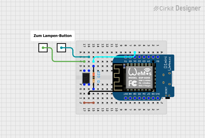
Circuit Diagram
- Input Side: Connect the anode to a digital pin on the Arduino through a 220 Ω resistor.
- Output Side: Connect the collector to a 5 V supply through a 10 kΩ pull-up resistor, and the emitter to ground.
Arduino Code
// Optocoupler Example with Arduino UNO
// This code reads the state of the optocoupler and toggles an LED accordingly.

const int optoInputPin = 2;  // Pin connected to the optocoupler output
const int ledPin = 13;       // Built-in LED pin on Arduino

void setup() {
  pinMode(optoInputPin, INPUT);  // Set optocoupler output pin as input
  pinMode(ledPin, OUTPUT);       // Set LED pin as output
}

void loop() {
  int optoState = digitalRead(optoInputPin);  // Read optocoupler state

  if (optoState == HIGH) {
    digitalWrite(ledPin, HIGH);  // Turn on LED if optocoupler output is HIGH
  } else {
    digitalWrite(ledPin, LOW);   // Turn off LED if optocoupler output is LOW
  }
}
Troubleshooting and FAQs
Common Issues and Solutions
LED Not Lighting Up:
- Check the input current and ensure the current-limiting resistor is correctly calculated.
- Verify the polarity of the LED connections (anode and cathode).
No Output Signal:
- Ensure the pull-up resistor is connected on the output side.
- Verify that the phototransistor is correctly connected (collector and emitter).
Signal Distortion or Noise:
- Use a capacitor across the pull-up resistor to filter noise.
- Ensure the optocoupler is not operating near its maximum response time limit.
Component Overheating:
- Check that the input and output currents do not exceed the maximum ratings.
- Verify that the isolation voltage is not being exceeded.
FAQs
Q: Can an optocoupler handle analog signals?
A: Yes, optocouplers can handle analog signals, but the linearity and bandwidth may be limited depending on the specific model.
Q: How do I choose the right optocoupler for my application?
A: Consider factors such as isolation voltage, response time, input/output current ratings, and whether you need a transistor, Darlington, or logic output.
Q: Can I use an optocoupler for bidirectional communication?
A: Standard optocouplers are unidirectional. For bidirectional communication, consider using two optocouplers or specialized isolators.
Q: What is the lifespan of an optocoupler?
A: Optocouplers have a long lifespan but may degrade over time due to LED aging. Ensure proper current limits to maximize lifespan.