How to Use Arduino Mega ADK (Rev3): Examples, Pinouts, and Specs
Introduction
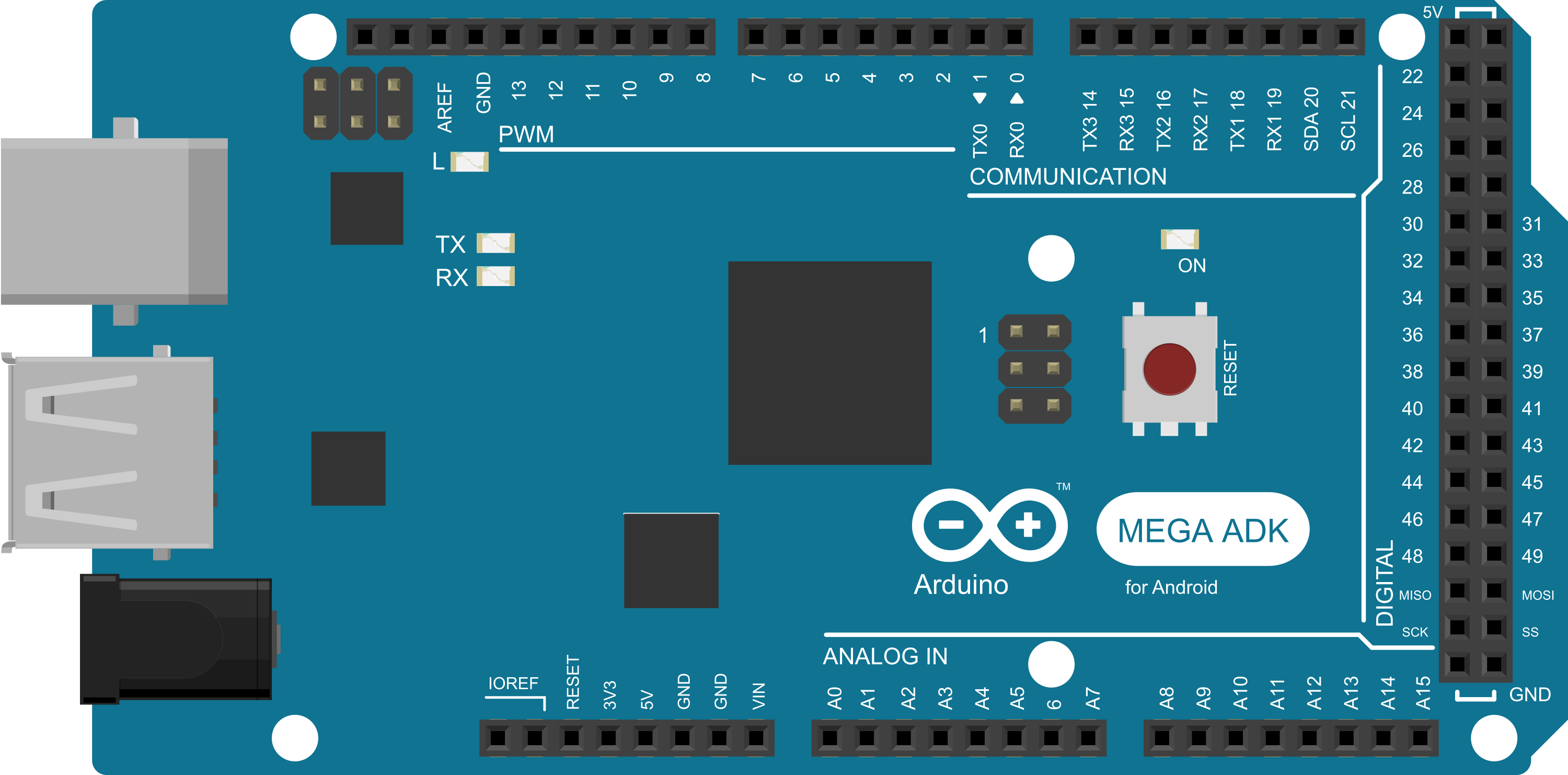
The Arduino Mega ADK (Rev3) is a microcontroller board based on the ATmega2560. It is designed to work with Android devices via its USB host interface, making it an ideal choice for developers looking to create Android-compatible hardware accessories. The board provides a vast array of I/O pins and increased memory capacity, which makes it suitable for larger and more complex projects that require additional computational power and connectivity options.
Explore Projects Built with Arduino Mega ADK (Rev3)
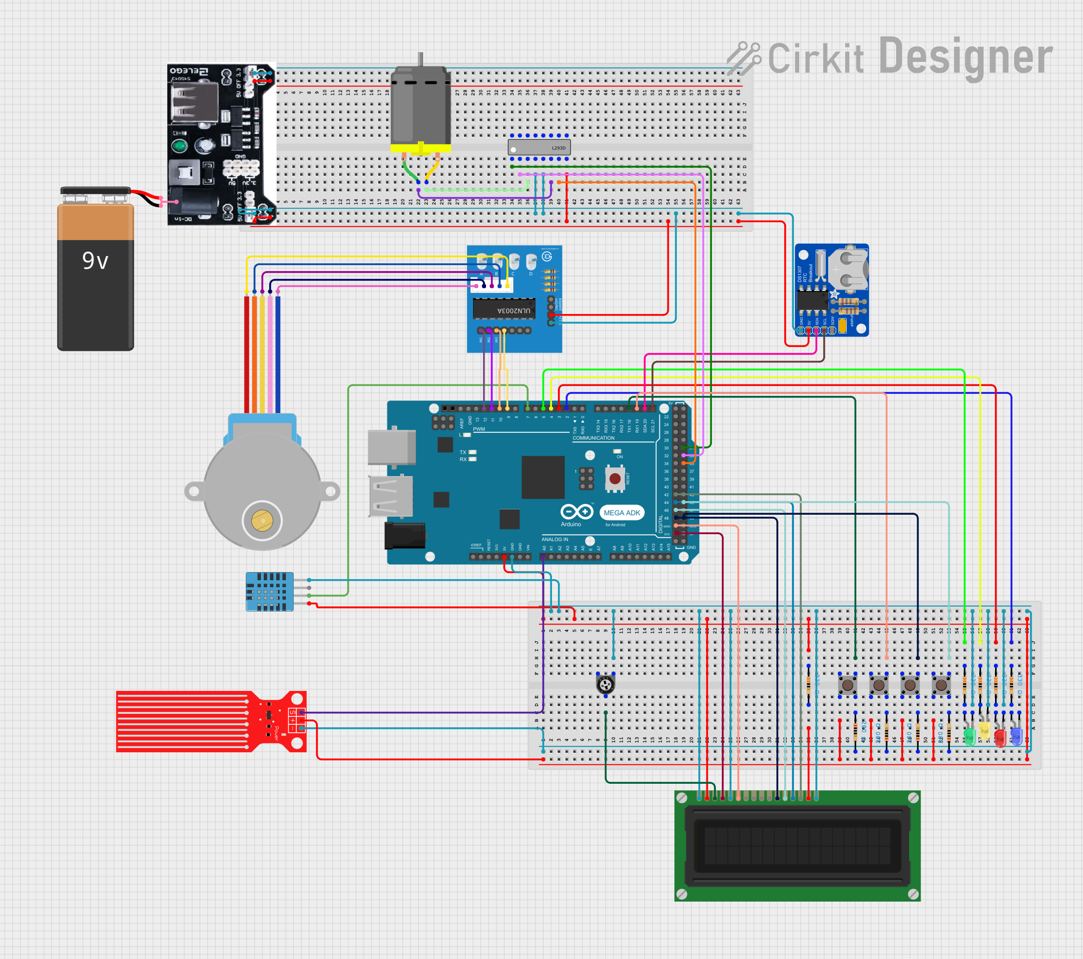
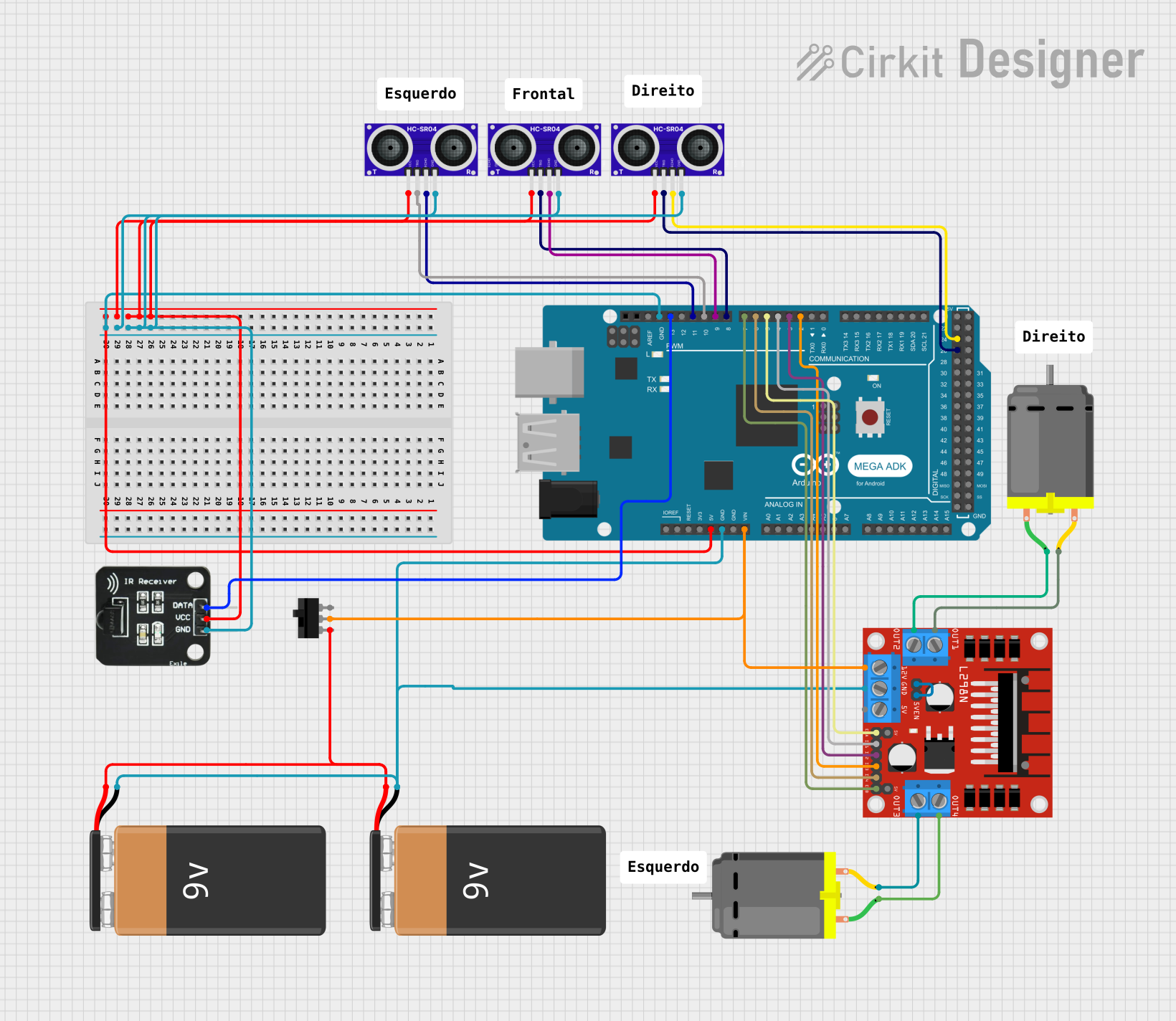
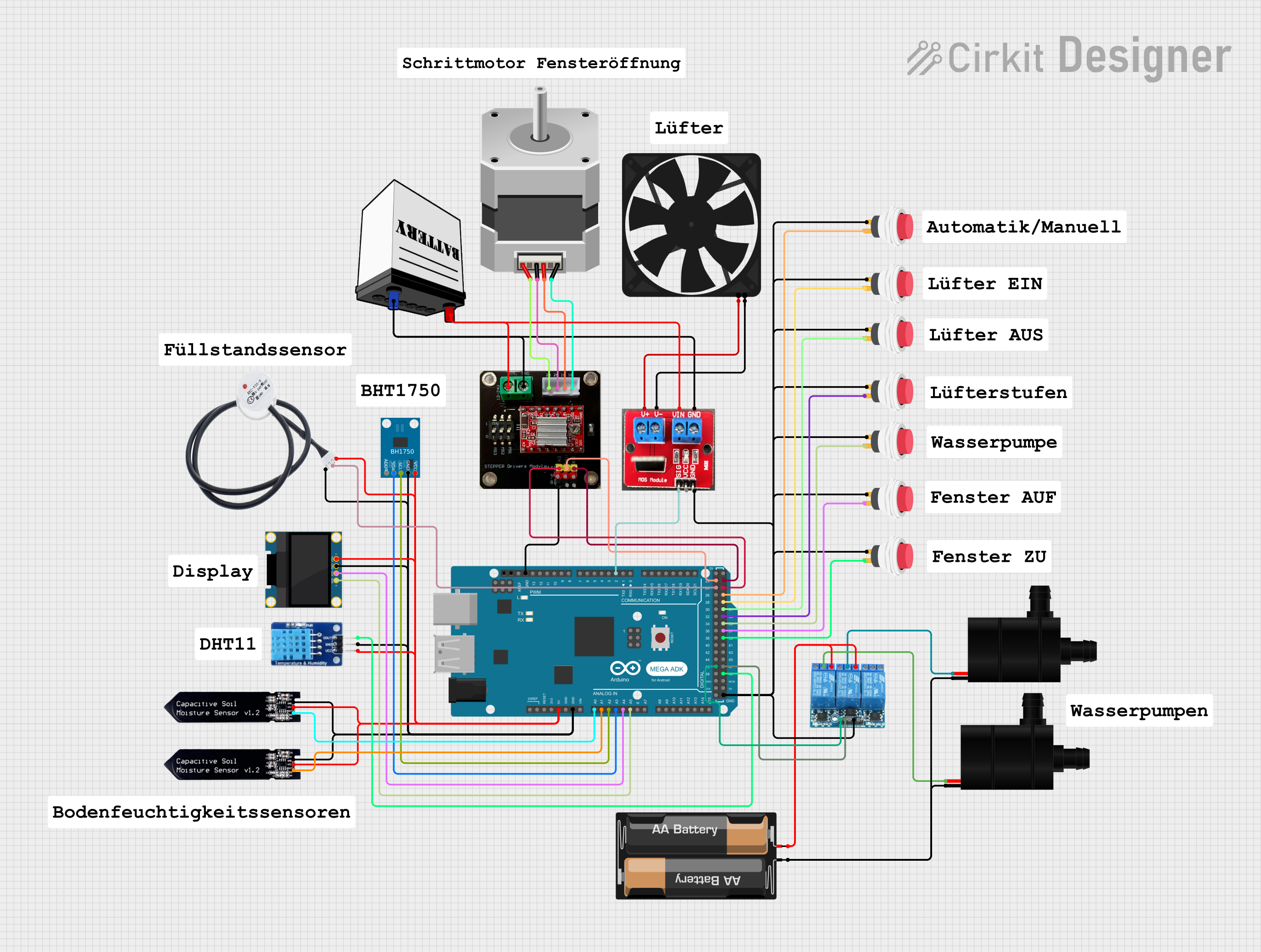
Explore Projects Built with Arduino Mega ADK (Rev3)
Common Applications and Use Cases
- Android accessory development
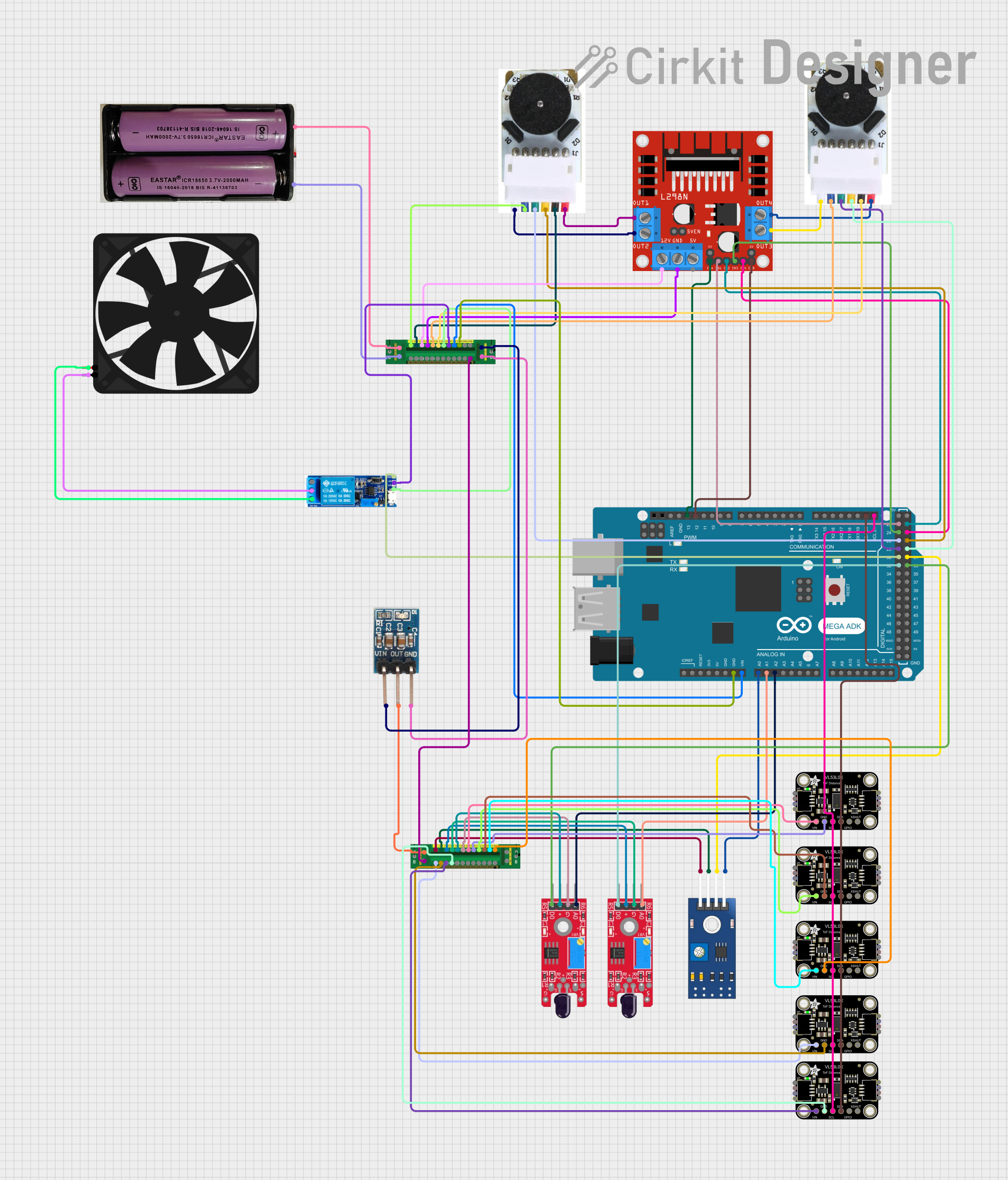
- Robotics and control systems
- Complex interactive artworks
- Home automation systems
- Prototyping of consumer electronics
- Educational projects and DIY experiments
Technical Specifications
Key Technical Details
- Microcontroller: ATmega2560
- Operating Voltage: 5V
- Input Voltage (recommended): 7-12V
- Input Voltage (limits): 6-20V
- Digital I/O Pins: 54 (of which 15 provide PWM output)
- Analog Input Pins: 16
- DC Current per I/O Pin: 20 mA
- DC Current for 3.3V Pin: 50 mA
- Flash Memory: 256 KB of which 8 KB used by bootloader
- SRAM: 8 KB
- EEPROM: 4 KB
- Clock Speed: 16 MHz
- USB Host: Yes
Pin Configuration and Descriptions
| Pin Number | Function | Description |
|---|---|---|
| 1-54 | Digital I/O | Digital input/output pins, PWM on 15 pins |
| A0-A15 | Analog Input | Analog input pins |
| GND | Ground | Ground pins |
| 5V | Power | Regulated power supply for the board |
| 3.3V | Power | 3.3V power supply derived from the onboard regulator |
| VIN | Voltage Input | Unregulated input voltage to the board |
| RESET | Reset | Resets the microcontroller |
Usage Instructions
How to Use the Component in a Circuit
Powering the Board:
- Connect a 7-12V power supply to the VIN and GND pins for optimal performance.
- Alternatively, you can power the board via the USB connection.
Connecting to Android Devices:
- Use the USB host port to connect the board to an Android device.
- Ensure your Android device supports USB host mode and the Android Open Accessory (AOA) protocol.
Programming the Board:
- Connect the board to your computer using a USB cable.
- Use the Arduino IDE to write and upload sketches to the board.
Using I/O Pins:
- Digital pins can be used as inputs or outputs. Use
pinMode(),digitalWrite(), anddigitalRead()functions in your sketches. - Analog pins are primarily used for input with the
analogRead()function.
- Digital pins can be used as inputs or outputs. Use
Important Considerations and Best Practices
- Always disconnect the board from power sources before making or altering connections.
- Ensure that the total current through all I/O pins does not exceed the specified limits.
- Use external power supplies when connecting components that draw more current than the board can provide.
- Avoid exposing the board to extreme temperatures, moisture, or dust.
Troubleshooting and FAQs
Common Issues
Board not recognized by the computer:
- Check the USB cable and connections.
- Ensure the correct drivers are installed.
- Try resetting the board or using a different USB port.
Sketch upload fails:
- Verify that the correct board and port are selected in the Arduino IDE.
- Check for errors in the code and ensure the bootloader is functioning.
Insufficient power to external components:
- Use an external power supply with adequate current rating.
- Check connections and the power supply voltage.
Solutions and Tips for Troubleshooting
- Always start by checking connections and ensuring that the board is properly powered.
- Consult the Arduino forums and community for support on specific issues.
- Use serial debugging (
Serial.print()) to track down issues in your code.
FAQs
Can I power the Arduino Mega ADK from the USB port?
- Yes, but for projects that require more power, an external power supply is recommended.
What is the maximum voltage that can be applied to the I/O pins?
- The maximum voltage for any I/O pin is 5V. Exceeding this voltage can damage the board.
How do I reset the board?
- Press the reset button on the board or open and close the serial port at 1200bps.
If you are connecting the Arduino Mega ADK to an Arduino UNO or using it in a setup that involves Arduino-compatible code, here is an example of a simple sketch that blinks an LED connected to pin 13:
// The setup function runs once when you press reset or power the board
void setup() {
  // Initialize digital pin 13 as an output.
  pinMode(13, OUTPUT);
}

// The loop function runs over and over again forever
void loop() {
  digitalWrite(13, HIGH);   // Turn the LED on (HIGH is the voltage level)
  delay(1000);              // Wait for a second
  digitalWrite(13, LOW);    // Turn the LED off by making the voltage LOW
  delay(1000);              // Wait for a second
}
Remember to include comments in your code to explain the functionality, and keep the line length of comments within 80 characters for better readability.