How to Use TTP223 : Examples, Pinouts, and Specs
Introduction
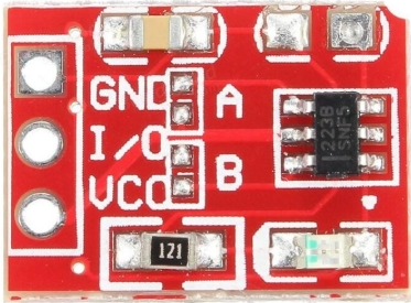
The TTP223 is a touch sensor IC manufactured by TouchSensor with the part ID TTP223-Touch. This component is designed to detect touch input and output a digital signal, making it an ideal choice for touch-sensitive applications. It enables the creation of touch-activated switches, controls, and interfaces, offering a modern and user-friendly alternative to traditional mechanical buttons.
Explore Projects Built with TTP223

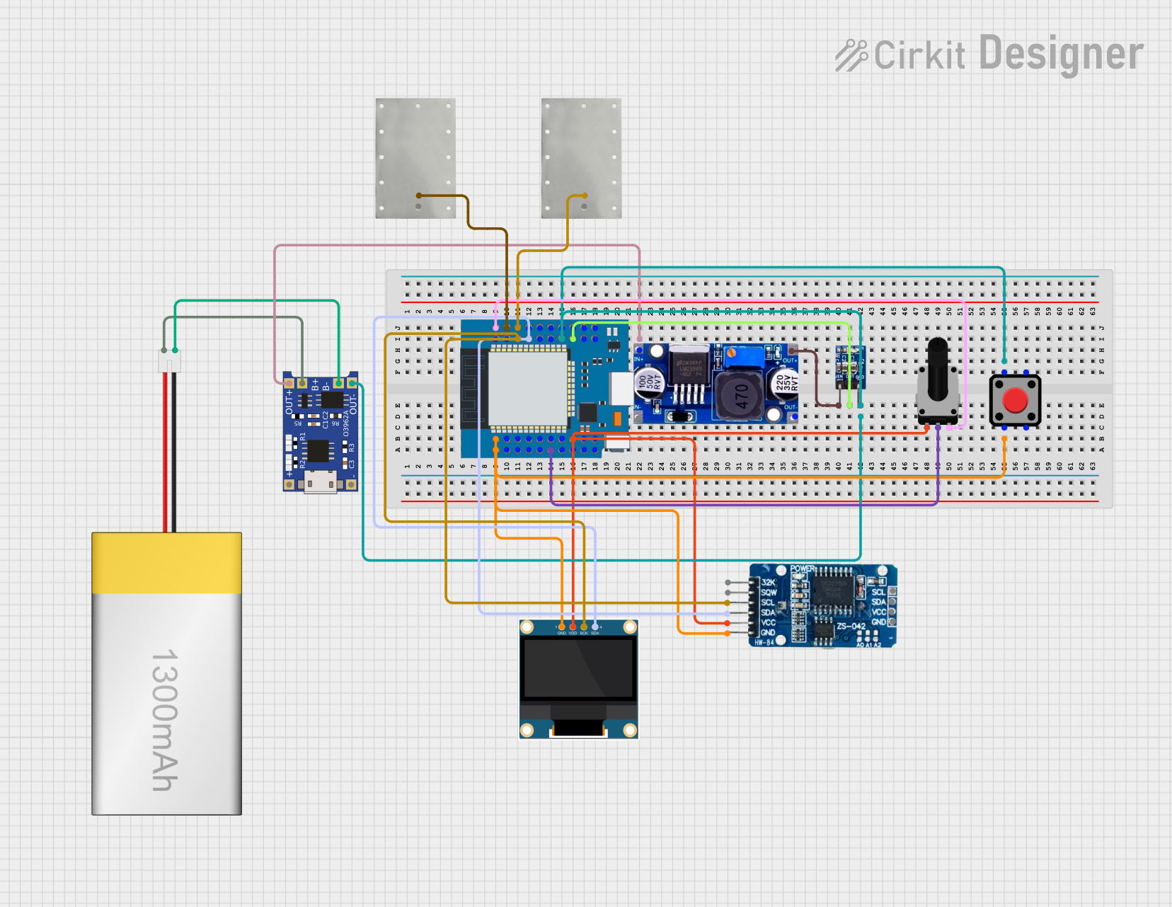
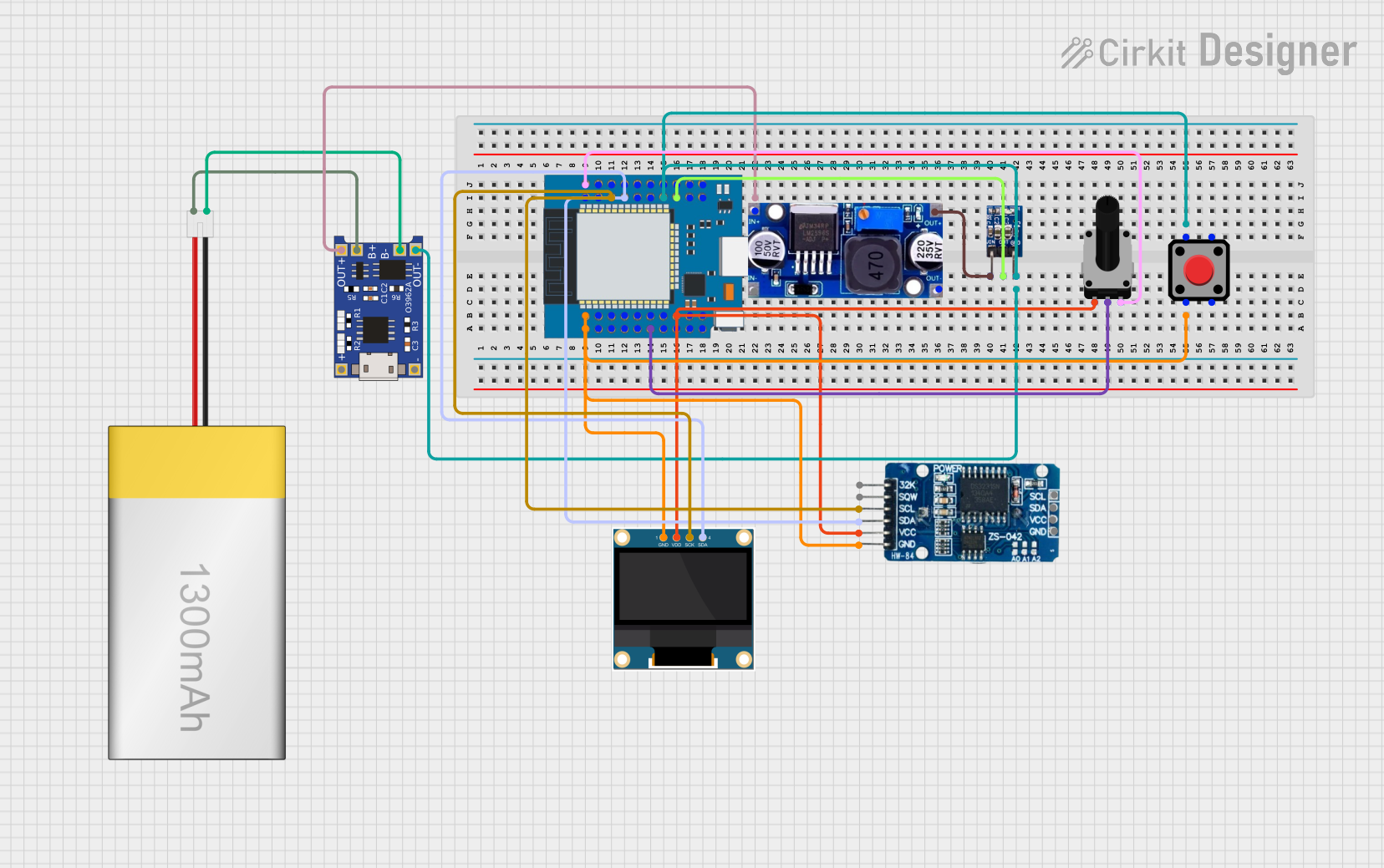

Explore Projects Built with TTP223
Common Applications
- Touch-sensitive light switches
- Capacitive touch panels
- Home automation systems
- Wearable devices
- Interactive displays
- DIY electronics projects
Technical Specifications
The TTP223 is a compact and efficient touch sensor IC with the following key specifications:
| Parameter | Value |
|---|---|
| Operating Voltage | 2.0V to 5.5V |
| Operating Current | 1.5µA (typical at 3V) |
| Response Time | ~60ms (fast mode) |
| Output Type | Digital (Active High) |
| Output Drive Capability | Up to 8mA |
| Touch Detection Distance | Up to 5mm (depending on material) |
| Operating Temperature | -40°C to +85°C |
| Package Type | SOT-23-6 or DIP-6 |
Pin Configuration and Descriptions
The TTP223 IC typically comes in a 6-pin package. Below is the pin configuration:
| Pin Number | Pin Name | Description |
|---|---|---|
| 1 | VDD | Power supply pin (2.0V to 5.5V). Connect to the positive terminal of the power source. |
| 2 | OUT | Digital output pin. Outputs HIGH when touch is detected, LOW otherwise. |
| 3 | AHLB | Active High/Low selection pin. Connect to GND for active high output. |
| 4 | MODE | Mode selection pin. Connect to GND for toggle mode or leave floating for momentary mode. |
| 5 | VSS | Ground pin. Connect to the negative terminal of the power source. |
| 6 | TP | Touch input pin. Connect to the touch-sensitive electrode or pad. |
Usage Instructions
How to Use the TTP223 in a Circuit
- Power Supply: Connect the VDD pin to a power source (2.0V to 5.5V) and the VSS pin to ground.
- Touch Electrode: Attach a conductive material (e.g., copper foil) to the TP pin to act as the touch-sensitive electrode.
- Output Connection: Connect the OUT pin to the input of a microcontroller or other digital logic circuit.
- Mode Selection:
- For momentary mode (output remains HIGH only while touch is detected), leave the MODE pin floating.
- For toggle mode (output toggles between HIGH and LOW with each touch), connect the MODE pin to ground.
- Active High/Low Selection:
- For active high output, connect the AHLB pin to ground.
- For active low output, leave the AHLB pin floating.
Example Circuit
Below is a simple circuit diagram for using the TTP223 with an Arduino UNO:
- Connections:
- TTP223 VDD → Arduino 5V
- TTP223 VSS → Arduino GND
- TTP223 OUT → Arduino digital pin (e.g., D2)
- TTP223 TP → Touch-sensitive electrode (e.g., copper foil)
Arduino Code Example
// TTP223 Touch Sensor Example with Arduino UNO
// This code reads the digital output from the TTP223 and toggles an LED.

#define TOUCH_PIN 2  // TTP223 OUT pin connected to Arduino digital pin 2
#define LED_PIN 13   // Built-in LED pin on Arduino UNO

void setup() {
  pinMode(TOUCH_PIN, INPUT);  // Set TOUCH_PIN as input
  pinMode(LED_PIN, OUTPUT);   // Set LED_PIN as output
  Serial.begin(9600);         // Initialize serial communication for debugging
}

void loop() {
  int touchState = digitalRead(TOUCH_PIN);  // Read the state of the touch sensor

  if (touchState == HIGH) {
    // If touch is detected, turn on the LED
    digitalWrite(LED_PIN, HIGH);
    Serial.println("Touch detected!");
  } else {
    // If no touch is detected, turn off the LED
    digitalWrite(LED_PIN, LOW);
  }

  delay(50);  // Small delay to debounce the touch input
}
Important Considerations
- Touch Electrode Design: The size and material of the touch electrode can affect sensitivity. Use a flat, conductive material for best results.
- Noise Reduction: Place a 0.1µF decoupling capacitor between VDD and VSS to reduce noise and improve stability.
- Touch Distance: The detection distance depends on the thickness and material of the overlay (e.g., plastic or glass) covering the electrode.
Troubleshooting and FAQs
Common Issues and Solutions
No Response from the Sensor:
- Ensure the power supply voltage is within the specified range (2.0V to 5.5V).
- Verify all connections, especially the touch electrode and ground.
False Touch Detection:
- Check for electrical noise in the circuit. Add a decoupling capacitor (0.1µF) between VDD and VSS.
- Ensure the touch electrode is not too large or too close to other conductive materials.
Output Signal is Unstable:
- Verify the mode selection and active high/low configuration pins are correctly connected.
- Avoid placing the sensor near high-frequency components or strong electromagnetic fields.
Touch Detection Distance is Too Short:
- Use a larger touch electrode or reduce the thickness of the overlay material.
- Ensure the overlay material is non-conductive and has a low dielectric constant.
FAQs
Q1: Can the TTP223 detect multiple touches simultaneously?
A1: No, the TTP223 is designed to detect a single touch input at a time.
Q2: What is the maximum detection distance?
A2: The detection distance can reach up to 5mm, depending on the size of the touch electrode and the overlay material.
Q3: Can I use the TTP223 with a 3.3V microcontroller?
A3: Yes, the TTP223 operates within a voltage range of 2.0V to 5.5V, making it compatible with 3.3V systems.
Q4: Is the TTP223 waterproof?
A4: The IC itself is not waterproof, but you can design a waterproof touch electrode by using a sealed overlay material.
Q5: Can I use the TTP223 for gesture recognition?
A5: No, the TTP223 is a simple touch sensor and does not support advanced features like gesture recognition.