How to Use DIP14: Examples, Pinouts, and Specs
Introduction
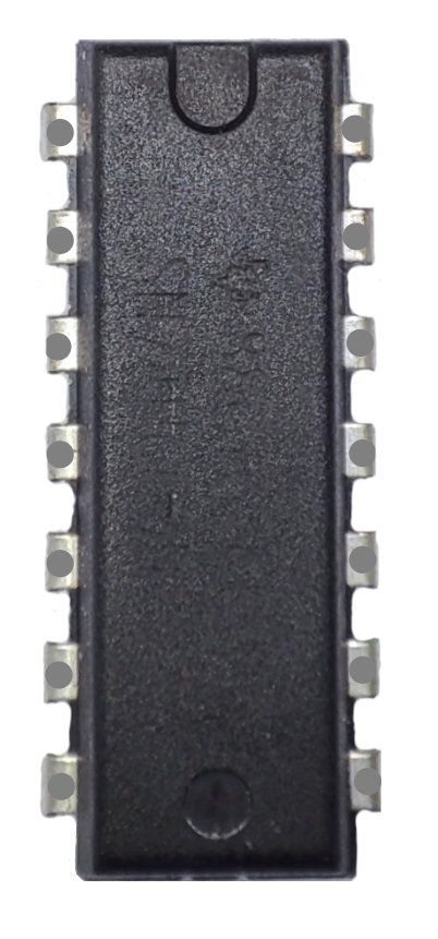
The DIP14 (Dual In-line Package with 14 pins) is a widely used packaging format for integrated circuits (ICs). It features two parallel rows of pins, making it easy to insert into a socket or solder onto a printed circuit board (PCB). The DIP14 package is commonly used for logic ICs, timers, microcontrollers, and other small-scale integrated circuits.
Explore Projects Built with DIP14


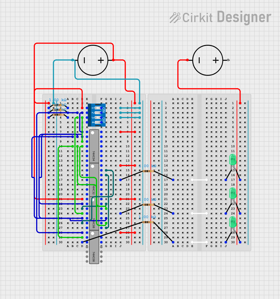
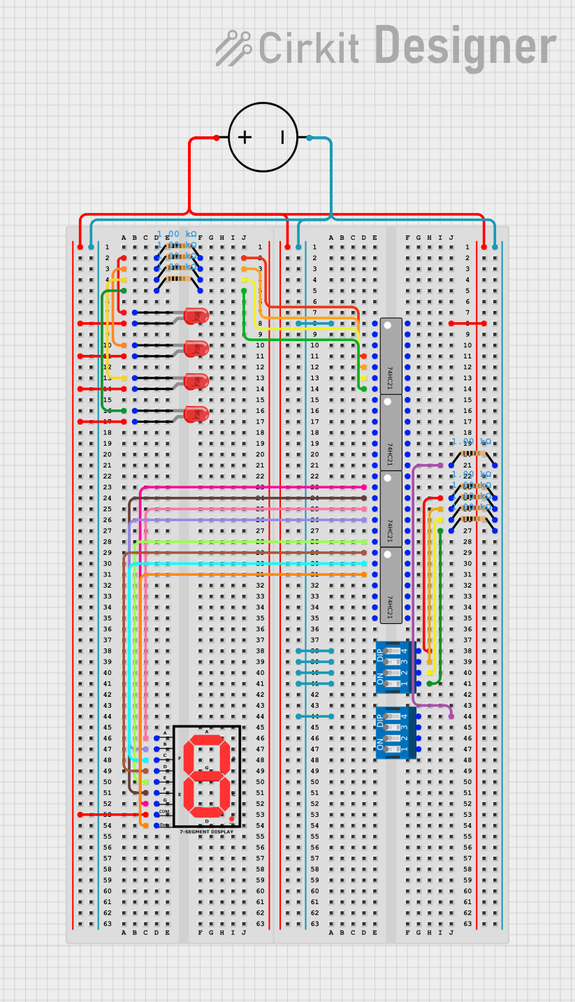
Explore Projects Built with DIP14
Common Applications and Use Cases
- Digital logic ICs (e.g., 74xx series logic gates)
- Analog ICs (e.g., operational amplifiers)
- Timers (e.g., NE555 timer IC)
- Microcontrollers and memory ICs
- Prototyping and breadboard-friendly circuit designs
Technical Specifications
The DIP14 package is standardized, but the specific technical details depend on the IC housed within the package. Below are general specifications for the DIP14 package:
- Number of Pins: 14 (7 pins on each side)
- Pin Pitch: 2.54 mm (0.1 inch)
- Row Spacing: 7.62 mm (0.3 inch)
- Body Width: Typically 7.62 mm to 10.16 mm
- Body Length: Approximately 19.3 mm
- Mounting Type: Through-hole
- Material: Plastic or ceramic body
Pin Configuration and Descriptions
The pin configuration of a DIP14 package depends on the specific IC it houses. Below is an example pinout for a common IC in a DIP14 package, the NE555 timer:
| Pin Number | Pin Name | Description |
|---|---|---|
| 1 | GND | Ground (0V reference) |
| 2 | TRIG | Trigger input for starting the timer |
| 3 | OUT | Output signal |
| 4 | RESET | Resets the timer (active low) |
| 5 | CTRL | Control voltage for modifying timing behavior |
| 6 | THR | Threshold input for comparison |
| 7 | DISCH | Discharge pin for timing capacitor |
| 8 | VCC | Positive supply voltage |
| 9-14 | (Varies by IC) | Reserved for other functions depending on IC |
For other ICs, refer to the specific datasheet for the pinout and functionality.
Usage Instructions
How to Use the DIP14 in a Circuit
- Insert into a Breadboard or Socket: The DIP14 package is designed for through-hole mounting. Align the pins with the holes in a breadboard or IC socket and gently press down.
- Connect Power and Ground: Identify the VCC (power) and GND (ground) pins from the IC datasheet and connect them to the appropriate voltage source.
- Connect Input and Output Pins: Wire the input and output pins according to the circuit design. Use pull-up or pull-down resistors if required.
- Soldering (Optional): If using a PCB, solder the pins to the board for a permanent connection.
Important Considerations and Best Practices
- Orientation: Ensure the IC is oriented correctly. The notch or dot on the package indicates Pin 1.
- Voltage Ratings: Verify the operating voltage range of the IC to avoid damage.
- Static Sensitivity: Handle the IC with care to prevent electrostatic discharge (ESD) damage.
- Decoupling Capacitors: Place a 0.1 µF ceramic capacitor close to the VCC and GND pins to stabilize the power supply.
Example: Using a DIP14 NE555 Timer with Arduino UNO
Below is an example of using a DIP14 NE555 timer IC to generate a square wave signal, which can be read by an Arduino UNO:
// Example: Reading a square wave signal from a NE555 timer with Arduino UNO
// Connect NE555 OUT pin to Arduino digital pin 2

const int inputPin = 2; // NE555 OUT pin connected to Arduino pin 2
int signalState = 0;    // Variable to store the signal state

void setup() {
  pinMode(inputPin, INPUT); // Set pin 2 as input
  Serial.begin(9600);       // Initialize serial communication
}

void loop() {
  signalState = digitalRead(inputPin); // Read the signal from NE555
  Serial.println(signalState);         // Print the signal state to Serial Monitor
  delay(100);                          // Small delay for readability
}
Troubleshooting and FAQs
Common Issues
IC Not Functioning:
- Cause: Incorrect orientation or improper connections.
- Solution: Double-check the pinout and ensure the IC is inserted correctly.
Overheating:
- Cause: Exceeding the voltage or current ratings.
- Solution: Verify the power supply voltage and current requirements of the IC.
No Output Signal:
- Cause: Missing or incorrect external components (e.g., resistors, capacitors).
- Solution: Refer to the IC datasheet for the recommended circuit configuration.
Loose Connections:
- Cause: Poor contact in the breadboard or socket.
- Solution: Ensure all pins are securely inserted and connections are tight.
FAQs
Q1: Can I use a DIP14 IC on a breadboard?
A1: Yes, the DIP14 package is breadboard-friendly due to its standard pin pitch of 2.54 mm.
Q2: How do I identify Pin 1 on a DIP14 IC?
A2: Look for a notch or dot on the IC package. Pin 1 is located to the left of the notch or next to the dot.
Q3: What is the maximum voltage for a DIP14 IC?
A3: The maximum voltage depends on the specific IC. Refer to the datasheet for the exact voltage rating.
Q4: Can I desolder and reuse a DIP14 IC?
A4: Yes, DIP14 ICs can be desoldered and reused if handled carefully to avoid damage.