How to Use esp32: Examples, Pinouts, and Specs
Introduction
The ESP32, manufactured by Espressif Systems, is a low-cost, low-power system on a chip (SoC) with integrated Wi-Fi and Bluetooth capabilities. It is designed for a wide range of applications, including Internet of Things (IoT) devices, smart home systems, wearable electronics, and industrial automation. The ESP32 is highly versatile, offering dual-core processing, a rich set of peripherals, and extensive connectivity options, making it a popular choice for both hobbyists and professionals.
Explore Projects Built with esp32


Explore Projects Built with esp32
Common Applications and Use Cases
- IoT devices and smart home automation
- Wireless sensor networks
- Wearable electronics
- Industrial control systems
- Robotics and drones
- Prototyping and educational projects
Technical Specifications
The ESP32 Dev Module is a feature-rich development board based on the ESP32 SoC. Below are its key technical specifications:
Key Technical Details
- Processor: Dual-core Xtensa® 32-bit LX6 microprocessor
- Clock Speed: Up to 240 MHz
- Flash Memory: 4 MB (varies by module)
- SRAM: 520 KB
- Connectivity: Wi-Fi 802.11 b/g/n, Bluetooth 4.2 (Classic and BLE)
- Operating Voltage: 3.3V
- GPIO Pins: 34 (multiplexed with other functions)
- ADC Channels: 18 (12-bit resolution)
- DAC Channels: 2 (8-bit resolution)
- PWM Channels: 16
- I2C Interfaces: 2
- SPI Interfaces: 4
- UART Interfaces: 3
- Power Consumption: Ultra-low power modes available
- Operating Temperature: -40°C to +125°C
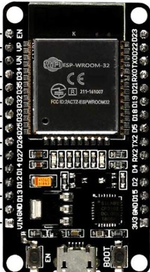
Pin Configuration and Descriptions
The ESP32 Dev Module has a variety of pins for different functionalities. Below is a summary of the pin configuration:
| Pin Name | Function | Description |
|---|---|---|
| GPIO0 | Input/Output, Boot Mode | Used for boot mode selection during startup. |
| GPIO2 | Input/Output, ADC, PWM | General-purpose I/O, supports ADC and PWM. |
| GPIO12 | Input/Output, ADC, Touch | General-purpose I/O, supports ADC and capacitive touch sensing. |
| GPIO13 | Input/Output, ADC, Touch | General-purpose I/O, supports ADC and capacitive touch sensing. |
| GPIO15 | Input/Output, ADC, PWM | General-purpose I/O, supports ADC and PWM. |
| EN | Enable | Active-high pin to enable or reset the module. |
| 3V3 | Power | 3.3V power supply input/output. |
| GND | Ground | Ground connection. |
| TX0 (GPIO1) | UART TX | UART transmit pin for serial communication. |
| RX0 (GPIO3) | UART RX | UART receive pin for serial communication. |
| VIN | Power | Input voltage (5V) for powering the module via an external source. |
Note: Many GPIO pins are multiplexed with other functions such as ADC, DAC, and touch sensing. Refer to the ESP32 datasheet for detailed pin mappings.
Usage Instructions
The ESP32 can be used in a variety of circuits and projects. Below are the steps to get started:
How to Use the ESP32 in a Circuit
Powering the ESP32:
- Use the VIN pin to supply 5V from an external source, or connect the module to a computer via USB.
- Ensure the 3.3V pin is not directly connected to a higher voltage source to avoid damage.
Connecting Peripherals:
- Use GPIO pins for digital input/output, ADC for analog input, and PWM for controlling devices like LEDs or motors.
- For communication, use UART, I2C, or SPI interfaces as needed.
Programming the ESP32:
- Install the Arduino IDE or ESP-IDF (Espressif IoT Development Framework).
- Add the ESP32 board package to the Arduino IDE via the Board Manager.
- Connect the ESP32 to your computer using a USB cable and select the appropriate COM port.
Uploading Code:
- Write your code in the Arduino IDE or ESP-IDF.
- Press the "Upload" button in the IDE to flash the code to the ESP32.
- If required, hold the "BOOT" button on the ESP32 during the upload process.
Important Considerations and Best Practices
- Voltage Levels: The ESP32 operates at 3.3V logic levels. Use level shifters if interfacing with 5V devices.
- Power Supply: Ensure a stable power supply to avoid unexpected resets or malfunctions.
- GPIO Usage: Avoid using GPIO6–GPIO11 as they are connected to the internal flash memory.
- Wi-Fi and Bluetooth: When using wireless features, ensure proper antenna placement for optimal signal strength.
Example Code for Arduino UNO Integration
Below is an example of how to blink an LED connected to GPIO2 of the ESP32:
// Example: Blink an LED on GPIO2 of the ESP32

// Define the GPIO pin for the LED
#define LED_PIN 2

void setup() {
  // Set the LED pin as an output
  pinMode(LED_PIN, OUTPUT);
}

void loop() {
  // Turn the LED on
  digitalWrite(LED_PIN, HIGH);
  delay(1000); // Wait for 1 second

  // Turn the LED off
  digitalWrite(LED_PIN, LOW);
  delay(1000); // Wait for 1 second
}
Tip: Ensure the LED is connected to GPIO2 with a current-limiting resistor (e.g., 220Ω) to prevent damage.
Troubleshooting and FAQs
Common Issues and Solutions
ESP32 Not Detected by Computer:
- Ensure the USB cable is functional and supports data transfer.
- Install the correct USB-to-serial driver for your operating system.
Code Upload Fails:
- Check the COM port and board settings in the Arduino IDE.
- Hold the "BOOT" button during the upload process if necessary.
Wi-Fi Connection Issues:
- Verify the SSID and password in your code.
- Ensure the router is within range and supports 2.4 GHz Wi-Fi.
Random Resets or Instability:
- Use a stable power supply with sufficient current (at least 500 mA).
- Avoid using GPIO6–GPIO11 for general-purpose tasks.
FAQs
Q: Can the ESP32 operate on battery power?
A: Yes, the ESP32 can be powered by batteries. Use a 3.7V LiPo battery with a voltage regulator to provide 3.3V.Q: How do I use the ESP32's Bluetooth functionality?
A: The ESP32 supports both Bluetooth Classic and BLE. Use theBluetoothSeriallibrary for Classic Bluetooth or theBLElibrary for BLE.Q: Can I use the ESP32 with sensors and modules designed for Arduino?
A: Yes, most Arduino-compatible sensors and modules can be used with the ESP32, but ensure proper voltage level conversion if required.
By following this documentation, you can effectively use the ESP32 in your projects and troubleshoot common issues. For advanced features, refer to the official Espressif documentation.