How to Use CPT 12V-5V CD/CD Converter: Examples, Pinouts, and Specs
Introduction
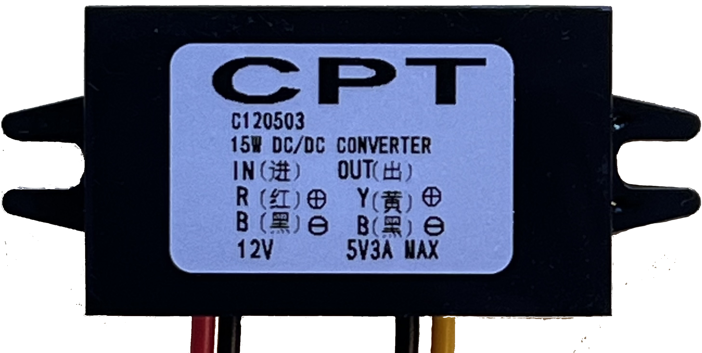
The CPT 12V-5V DC/DC Converter (Manufacturer Part ID: C120503) is a compact and efficient step-down voltage regulator designed to convert a 12V DC input to a stable 5V DC output. This component is widely used in applications where devices operating at 5V need to be powered from a 12V power source, such as in automotive systems, industrial equipment, and embedded electronics.
Explore Projects Built with CPT 12V-5V CD/CD Converter

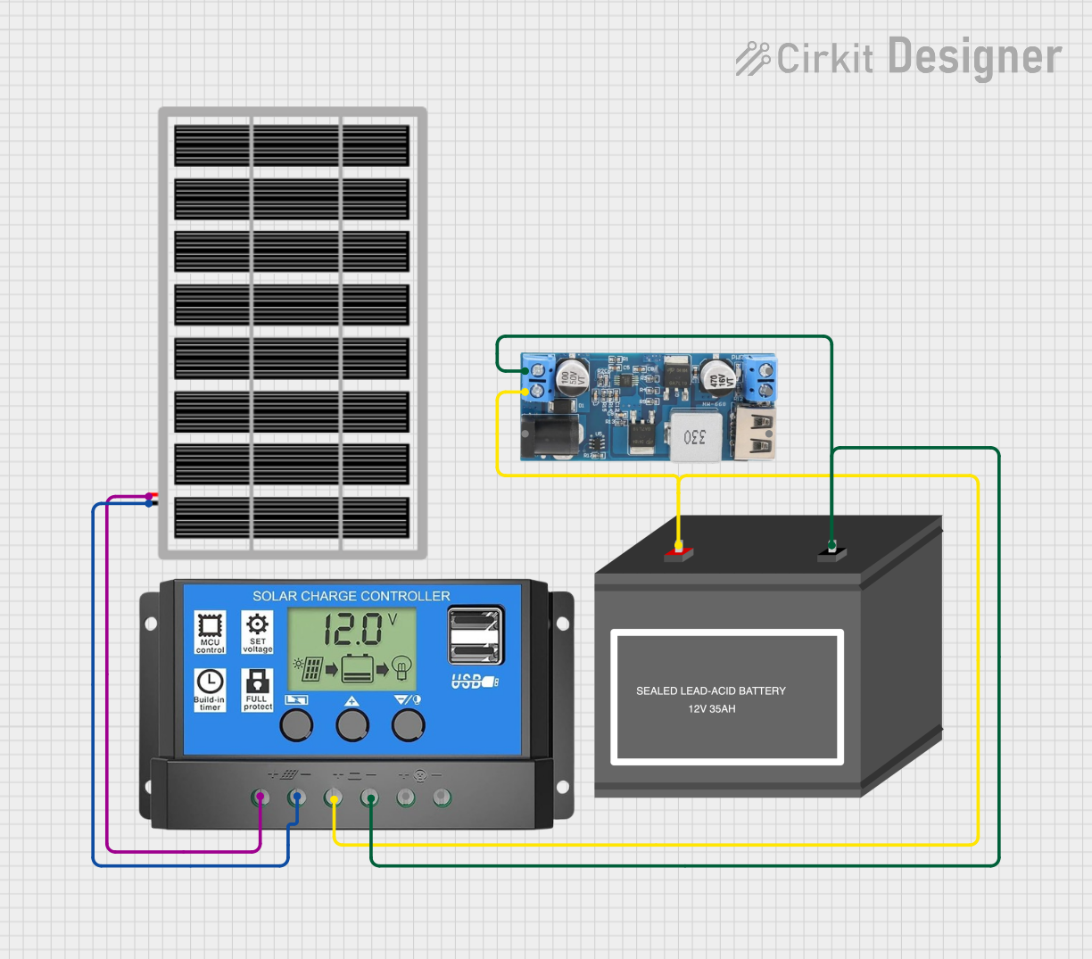


Explore Projects Built with CPT 12V-5V CD/CD Converter
Common Applications and Use Cases
- Powering 5V microcontrollers (e.g., Arduino, Raspberry Pi) from a 12V source.
- Supplying power to USB devices in automotive environments.
- Voltage regulation in battery-powered systems.
- General-purpose voltage step-down for embedded systems.
Technical Specifications
The following table outlines the key technical details of the CPT 12V-5V DC/DC Converter:
| Parameter | Value |
|---|---|
| Input Voltage Range | 8V to 23V DC |
| Output Voltage | 5V DC |
| Output Current | Up to 3A |
| Efficiency | Up to 96% |
| Operating Temperature | -40°C to +85°C |
| Dimensions | 46mm x 27mm x 14mm |
| Weight | Approximately 20g |
Pin Configuration and Descriptions
The CPT 12V-5V DC/DC Converter has four pins for input and output connections. The pin configuration is as follows:
| Pin | Name | Description |
|---|---|---|
| 1 | VIN+ | Positive input voltage (8V to 23V DC). |
| 2 | VIN- | Negative input voltage (ground). |
| 3 | VOUT+ | Positive output voltage (5V DC). |
| 4 | VOUT- | Negative output voltage (ground). |
Usage Instructions
How to Use the Component in a Circuit
Connect the Input Voltage:
- Connect the VIN+ pin to the positive terminal of your 12V power source.
- Connect the VIN- pin to the ground of your power source.
Connect the Output Voltage:
- Connect the VOUT+ pin to the positive terminal of the device requiring 5V.
- Connect the VOUT- pin to the ground of the device.
Verify Connections:
- Double-check all connections to ensure proper polarity and avoid short circuits.
Power On:
- Turn on the 12V power source. The converter will regulate the input voltage and provide a stable 5V output.
Important Considerations and Best Practices
- Heat Dissipation: Ensure adequate ventilation or heat sinking if the converter operates near its maximum current rating (3A).
- Input Voltage Range: Do not exceed the specified input voltage range (8V to 23V) to prevent damage to the component.
- Load Requirements: Ensure the connected load does not exceed the maximum output current (3A).
- Polarity Protection: Double-check the polarity of input and output connections to avoid damage.
Example: Using with an Arduino UNO
The CPT 12V-5V DC/DC Converter can be used to power an Arduino UNO from a 12V source. Below is an example circuit and Arduino code:
Circuit Connections
- Connect the VIN+ pin of the converter to the 12V power source.
- Connect the VIN- pin of the converter to the ground of the power source.
- Connect the VOUT+ pin of the converter to the 5V pin of the Arduino UNO.
- Connect the VOUT- pin of the converter to the GND pin of the Arduino UNO.
Arduino Code Example
// Example code to blink an LED connected to pin 13 of the Arduino UNO
// Ensure the Arduino is powered via the CPT 12V-5V DC/DC Converter

void setup() {
  pinMode(13, OUTPUT); // Set pin 13 as an output pin
}

void loop() {
  digitalWrite(13, HIGH); // Turn the LED on
  delay(1000);            // Wait for 1 second
  digitalWrite(13, LOW);  // Turn the LED off
  delay(1000);            // Wait for 1 second
}
Troubleshooting and FAQs
Common Issues and Solutions
No Output Voltage:
- Cause: Incorrect input connections or insufficient input voltage.
- Solution: Verify that the VIN+ and VIN- pins are connected correctly and that the input voltage is within the specified range (8V to 23V).
Overheating:
- Cause: Excessive load current or poor ventilation.
- Solution: Reduce the load current or improve ventilation around the converter.
Output Voltage Fluctuations:
- Cause: Unstable input voltage or excessive load.
- Solution: Ensure the input voltage is stable and within range. Check that the load does not exceed 3A.
Damaged Converter:
- Cause: Reverse polarity or input voltage exceeding the maximum rating.
- Solution: Replace the converter and ensure proper polarity and voltage range in future use.
FAQs
Q: Can this converter power a Raspberry Pi?
A: Yes, the CPT 12V-5V DC/DC Converter can power a Raspberry Pi, provided the total current draw does not exceed 3A.
Q: Is the converter waterproof?
A: No, the converter is not waterproof. It should be used in a dry environment or enclosed in a waterproof housing if necessary.
Q: Can I use this converter with a 24V input?
A: No, the maximum input voltage is 23V. Using a 24V input may damage the converter.
Q: Does the converter have short-circuit protection?
A: Yes, the converter includes built-in short-circuit and overcurrent protection for safe operation.