How to Use 4-Channel Encoded Motor Drive Module: Examples, Pinouts, and Specs
4-Channel Encoded Motor Drive Module Documentation
1. Introduction
The 4-Channel Encoded Motor Drive Module is a versatile motor control module designed to drive and control up to four DC motors with encoder feedback. This module enables precise control of motor speed, direction, and position by utilizing encoder signals for closed-loop feedback. It is ideal for robotics, automation systems, and other applications requiring accurate motor control.
Common Applications:
- Robotics (e.g., robotic arms, mobile robots)
- Conveyor belt systems
- Automated guided vehicles (AGVs)
- CNC machines
- Precision positioning systems
This module is compatible with microcontrollers such as Arduino, Raspberry Pi, and other development boards, making it a popular choice for hobbyists and professionals alike.
2. Technical Specifications
The following table outlines the key technical specifications of the 4-Channel Encoded Motor Drive Module:
| Parameter | Specification |
|---|---|
| Operating Voltage | 6V - 24V DC |
| Maximum Output Current | 2A per channel |
| Control Interface | PWM (Pulse Width Modulation) and Direction pins |
| Encoder Input | Quadrature encoder signals (A and B channels) |
| Motor Channels | 4 independent motor channels |
| Logic Voltage | 3.3V or 5V (compatible with most microcontrollers) |
| Communication Protocol | Optional UART/I2C for advanced control (if supported) |
| Dimensions | 60mm x 50mm x 15mm |
| Mounting Holes | 4 x M3 holes for secure mounting |
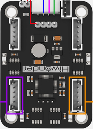
Pin Configuration and Descriptions
The module has multiple pins for motor control, encoder feedback, and power connections. The table below describes the pin configuration:
| Pin Name | Type | Description |
|---|---|---|
| VM | Power Input | Motor power supply (6V - 24V DC). Connect to an external power source. |
| GND | Ground | Common ground for power and logic. |
| VCC | Power Input | Logic voltage input (3.3V or 5V). |
| M1_PWM | Input | PWM signal for Motor 1 speed control. |
| M1_DIR | Input | Direction control for Motor 1. |
| M1_ENC_A | Input | Encoder channel A for Motor 1. |
| M1_ENC_B | Input | Encoder channel B for Motor 1. |
| M2_PWM | Input | PWM signal for Motor 2 speed control. |
| M2_DIR | Input | Direction control for Motor 2. |
| M2_ENC_A | Input | Encoder channel A for Motor 2. |
| M2_ENC_B | Input | Encoder channel B for Motor 2. |
| M3_PWM | Input | PWM signal for Motor 3 speed control. |
| M3_DIR | Input | Direction control for Motor 3. |
| M3_ENC_A | Input | Encoder channel A for Motor 3. |
| M3_ENC_B | Input | Encoder channel B for Motor 3. |
| M4_PWM | Input | PWM signal for Motor 4 speed control. |
| M4_DIR | Input | Direction control for Motor 4. |
| M4_ENC_A | Input | Encoder channel A for Motor 4. |
| M4_ENC_B | Input | Encoder channel B for Motor 4. |
3. Usage Instructions
Connecting the Module to an Arduino UNO
Power Supply:
- Connect the
VMpin to an external DC power source (6V - 24V). - Connect the
GNDpin to the ground of the power source and the Arduino.
- Connect the
Logic Voltage:
- Connect the
VCCpin to the 5V pin on the Arduino UNO.
- Connect the
Motor Connections:
- Connect the motor terminals to the motor output pins on the module.
Control Pins:
- Connect the
PWMandDIRpins for each motor to the corresponding Arduino digital pins. - Connect the encoder pins (
ENC_AandENC_B) to Arduino interrupt-capable pins for feedback.
- Connect the
Example Circuit Diagram
Below is a simplified connection example for controlling one motor with an encoder:
- Motor 1:
M1_PWM→ Arduino Pin 9M1_DIR→ Arduino Pin 8M1_ENC_A→ Arduino Pin 2 (interrupt pin)M1_ENC_B→ Arduino Pin 3 (interrupt pin)
Sample Arduino Code
The following code demonstrates how to control a motor with encoder feedback using the module:
// Define motor control pins
#define M1_PWM 9  // PWM pin for Motor 1
#define M1_DIR 8  // Direction pin for Motor 1

// Define encoder pins
#define M1_ENC_A 2  // Encoder channel A for Motor 1
#define M1_ENC_B 3  // Encoder channel B for Motor 1

// Variables for encoder position tracking
volatile long encoderPosition = 0;

// Interrupt service routine for encoder channel A
void encoderISR() {
  // Read the direction of rotation based on channel B
  if (digitalRead(M1_ENC_B) == HIGH) {
    encoderPosition++;
  } else {
    encoderPosition--;
  }
}

void setup() {
  // Set motor control pins as outputs
  pinMode(M1_PWM, OUTPUT);
  pinMode(M1_DIR, OUTPUT);

  // Set encoder pins as inputs
  pinMode(M1_ENC_A, INPUT);
  pinMode(M1_ENC_B, INPUT);

  // Attach interrupt to encoder channel A
  attachInterrupt(digitalPinToInterrupt(M1_ENC_A), encoderISR, CHANGE);

  // Initialize serial communication for debugging
  Serial.begin(9600);
}

void loop() {
  // Set motor direction (HIGH = forward, LOW = reverse)
  digitalWrite(M1_DIR, HIGH);

  // Set motor speed (0-255)
  analogWrite(M1_PWM, 150);

  // Print encoder position to the serial monitor
  Serial.print("Encoder Position: ");
  Serial.println(encoderPosition);

  delay(100);  // Delay for readability
}
Important Considerations:
- Ensure the motor power supply voltage matches the motor's rated voltage.
- Use appropriate decoupling capacitors to reduce noise in the circuit.
- Avoid exceeding the maximum current rating (2A per channel) to prevent damage.
- Use heat sinks or cooling if operating at high currents for extended periods.
4. Troubleshooting and FAQs
Common Issues and Solutions
| Issue | Possible Cause | Solution |
|---|---|---|
| Motor does not spin | Incorrect wiring or insufficient power | Verify all connections and ensure the power supply meets the voltage/current requirements. |
| Encoder feedback not working | Encoder pins not connected properly | Check encoder connections and ensure they are connected to interrupt-capable pins. |
| Motor spins in the wrong direction | Direction pin logic is inverted | Reverse the logic on the DIR pin or swap motor terminals. |
| Module overheating | Exceeding current rating | Reduce motor load or add heat sinks to the module. |
| Erratic motor behavior | Electrical noise or unstable power supply | Add decoupling capacitors and ensure a stable power source. |
Frequently Asked Questions (FAQs)
Can I use this module with stepper motors?
- No, this module is designed for DC motors with encoders. Stepper motors require a dedicated stepper driver.
What is the maximum encoder resolution supported?
- The module supports standard quadrature encoders. The resolution depends on the microcontroller's interrupt handling capability.
Can I control all four motors simultaneously?
- Yes, you can control all four motors independently using separate PWM, direction, and encoder pins.
Is this module compatible with 3.3V logic?
- Yes, the module supports both 3.3V and 5V logic levels.
This documentation provides a comprehensive guide to using the 4-Channel Encoded Motor Drive Module. For further assistance, refer to the module's datasheet or contact the manufacturer.
Explore Projects Built with 4-Channel Encoded Motor Drive Module
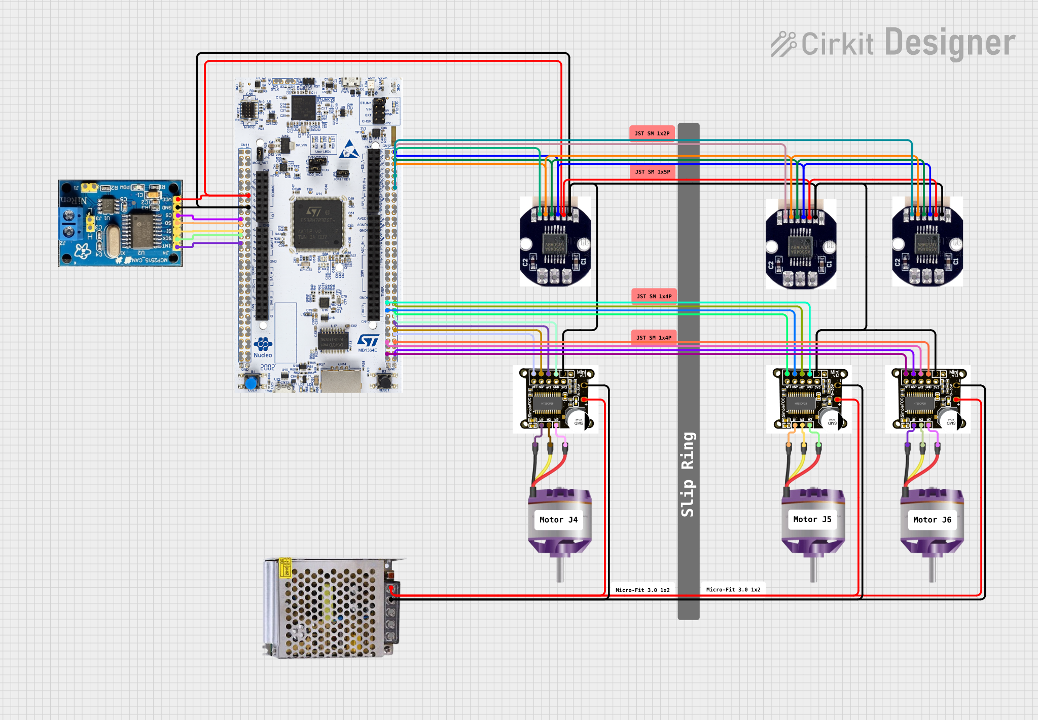


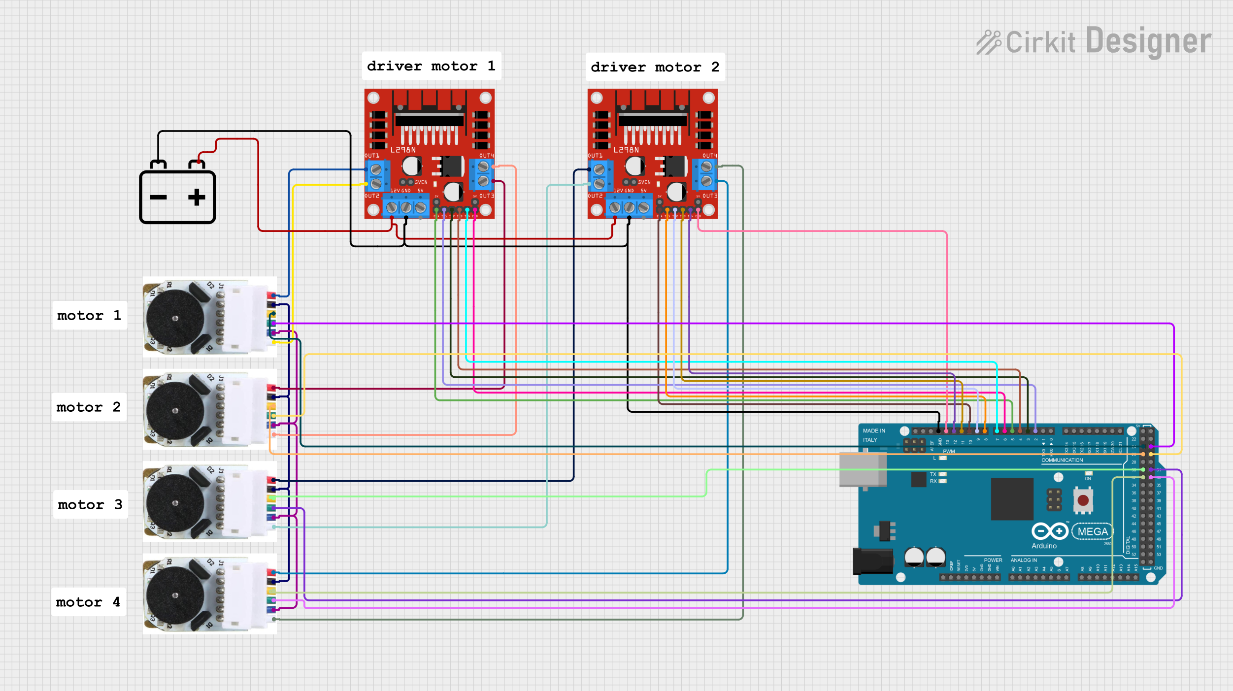
Explore Projects Built with 4-Channel Encoded Motor Drive Module