How to Use Button S/R1/-: Examples, Pinouts, and Specs
Introduction
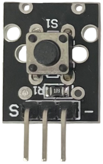
The Button S/R1/-, manufactured by Arduino, is a momentary switch designed to control the flow of current in a circuit. It is commonly used to start or stop devices, trigger events, or provide user input in electronic systems. This versatile component is ideal for applications requiring a simple and reliable interface for user interaction.
Explore Projects Built with Button S/R1/-


Explore Projects Built with Button S/R1/-
Common Applications and Use Cases
- User input for microcontroller-based projects (e.g., Arduino, Raspberry Pi)
- On/off control for small devices
- Reset or interrupt buttons in circuits
- Triggering events in automation systems
- Prototyping and educational projects
Technical Specifications
The Button S/R1/- is a compact and durable momentary switch with the following specifications:
| Parameter | Value |
|---|---|
| Operating Voltage | 3.3V to 5V |
| Maximum Current Rating | 50mA |
| Contact Resistance | ≤ 100mΩ |
| Insulation Resistance | ≥ 100MΩ |
| Operating Temperature | -20°C to +70°C |
| Dimensions | 6mm x 6mm x 5mm |
| Actuation Force | 160gf ± 50gf |
| Lifespan | 100,000 cycles |
Pin Configuration and Descriptions
The Button S/R1/- has four pins, arranged in a square configuration. However, only two pins are electrically connected at any given time, depending on the button's state (pressed or unpressed). The pin configuration is as follows:
| Pin Number | Description |
|---|---|
| Pin 1 | Normally Open (NO) terminal |
| Pin 2 | Normally Open (NO) terminal |
| Pin 3 | Connected internally to Pin 1 |
| Pin 4 | Connected internally to Pin 2 |
Note: Pins 1 and 3 are internally connected, as are Pins 2 and 4. This allows for flexible placement in a circuit.
Usage Instructions
How to Use the Button S/R1/- in a Circuit
Connect the Button:
- Identify the two pairs of internally connected pins (Pins 1 & 3, and Pins 2 & 4).
- Connect one pair to the input signal or microcontroller pin.
- Connect the other pair to ground or the desired circuit path.
Pull-Up or Pull-Down Resistor:
- Use a pull-up resistor (typically 10kΩ) to ensure a stable HIGH signal when the button is not pressed.
- Alternatively, use a pull-down resistor to ensure a stable LOW signal when the button is not pressed.
Debouncing:
- Implement hardware or software debouncing to eliminate noise caused by rapid mechanical contacts when the button is pressed or released.
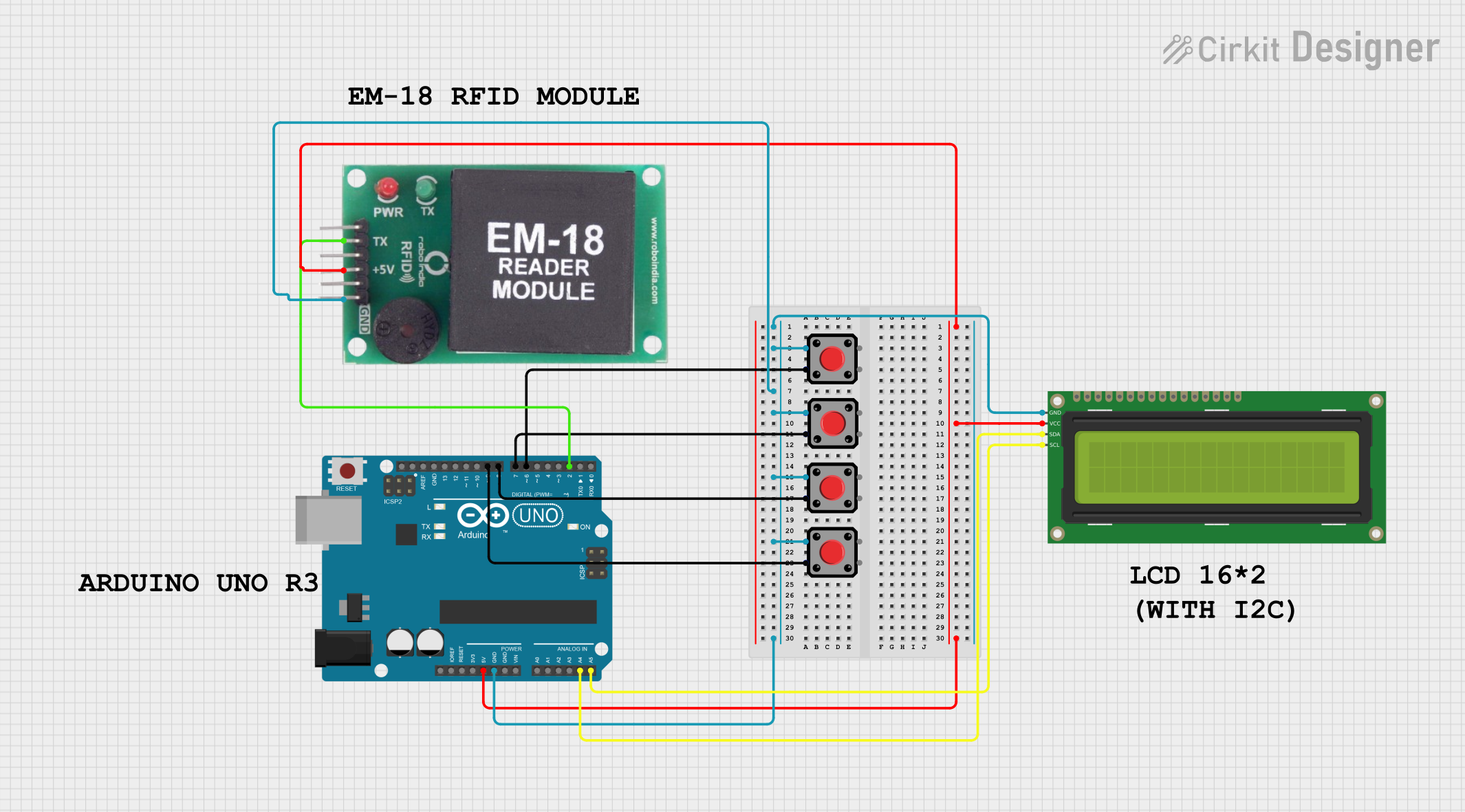
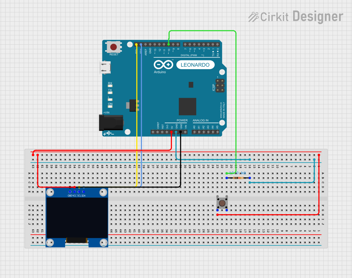
Example Circuit with Arduino UNO
Below is an example of how to connect the Button S/R1/- to an Arduino UNO and read its state:
Circuit Connections:
- Connect one terminal of the button to digital pin 2 on the Arduino.
- Connect the other terminal to ground.
- Use the Arduino's internal pull-up resistor to simplify the circuit.
Arduino Code:
// Button S/R1/- Example Code
// This code reads the state of the button and turns on an LED when pressed.

const int buttonPin = 2;  // Pin connected to the button
const int ledPin = 13;    // Pin connected to the onboard LED

void setup() {
  pinMode(buttonPin, INPUT_PULLUP); // Enable internal pull-up resistor
  pinMode(ledPin, OUTPUT);          // Set LED pin as output
}

void loop() {
  int buttonState = digitalRead(buttonPin); // Read the button state

  if (buttonState == LOW) { // Button is pressed (LOW due to pull-up resistor)
    digitalWrite(ledPin, HIGH); // Turn on the LED
  } else {
    digitalWrite(ledPin, LOW);  // Turn off the LED
  }
}
Important Considerations and Best Practices
- Debouncing: Always account for switch bounce in your design. Use a capacitor or software logic to filter out noise.
- Voltage Levels: Ensure the operating voltage matches the specifications (3.3V to 5V).
- Current Limiting: Avoid exceeding the maximum current rating (50mA) to prevent damage.
- Placement: Avoid placing the button in areas prone to excessive heat or moisture.
Troubleshooting and FAQs
Common Issues and Solutions
Button Not Responding:
- Cause: Incorrect wiring or loose connections.
- Solution: Double-check the wiring and ensure all connections are secure.
Button State Fluctuates (Noisy Signal):
- Cause: Switch bounce or lack of pull-up/pull-down resistor.
- Solution: Add a pull-up or pull-down resistor and implement debouncing.
Button Works Intermittently:
- Cause: Worn-out contacts or excessive force applied.
- Solution: Replace the button if it has exceeded its lifespan or is physically damaged.
Arduino Not Detecting Button Press:
- Cause: Incorrect pin configuration or missing pull-up resistor.
- Solution: Verify the pinMode configuration and ensure the pull-up resistor is enabled.
FAQs
Q: Can I use the Button S/R1/- with 12V circuits?
A: No, the button is designed for low-voltage applications (3.3V to 5V). Using it with higher voltages may damage the component.
Q: How do I implement hardware debouncing?
A: Connect a small capacitor (e.g., 0.1µF) across the button terminals to filter out noise caused by switch bounce.
Q: Can I use this button for high-frequency switching?
A: The Button S/R1/- is not suitable for high-frequency switching due to its mechanical nature. Use electronic switches or relays for such applications.
Q: Is the button waterproof?
A: No, the Button S/R1/- is not waterproof. Avoid exposing it to moisture or liquids.
By following this documentation, you can effectively integrate the Button S/R1/- into your projects and troubleshoot any issues that arise.