How to Use DRV 8825: Examples, Pinouts, and Specs
Introduction
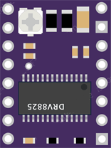
The DRV8825 is a stepper motor driver module designed by Texas Instruments, which allows for precise control of stepper motors in a wide range of applications. It is commonly used in 3D printers, CNC machines, and other automated equipment where precise motor control is required. The module can handle up to 2.5A per phase without a heat sink and operates from 8.2V to 45V, making it suitable for driving a wide range of stepper motors.
Explore Projects Built with DRV 8825
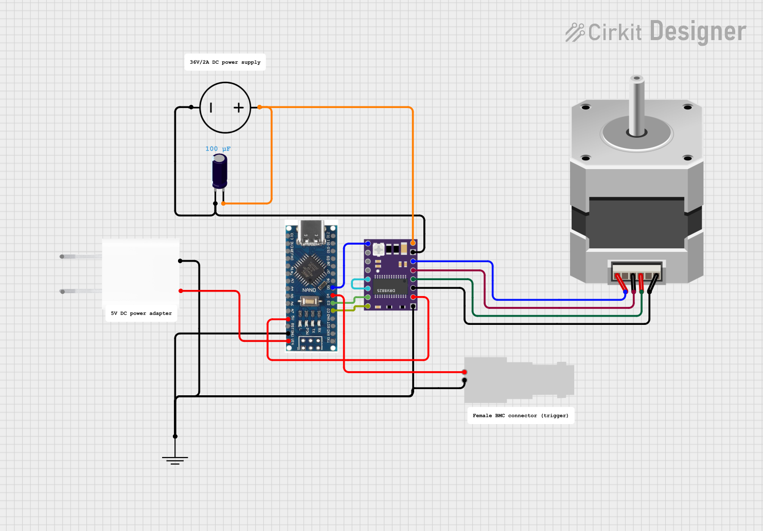

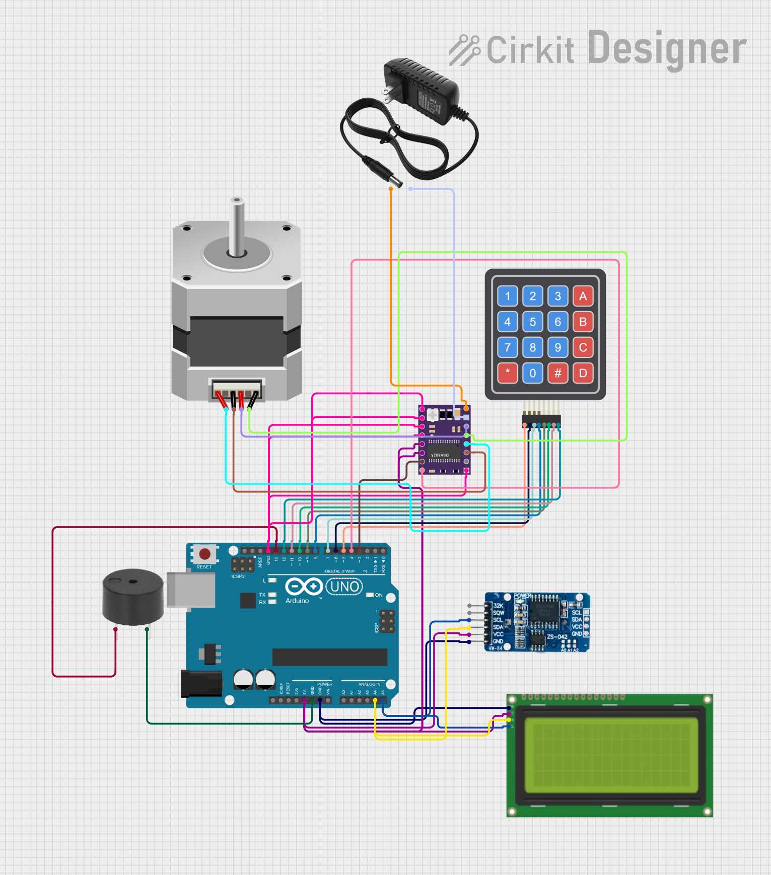

Explore Projects Built with DRV 8825
Technical Specifications
Key Technical Details
- Motor Supply Voltage (VM): 8.2 V to 45 V
- Output Current: 1.5 A per coil without a heat sink (2.5 A with sufficient additional cooling)
- Logic Voltage (VDD): 2.5 V to 5.25 V
- Microstep Resolutions: Full, 1/2, 1/4, 1/8, 1/16, 1/32
- Thermal Overload Protection: Yes
- Under-voltage Lockout: Yes
- Crossover-Current Protection: Yes
- Fault Indicator: Yes (FAULT output pin)
Pin Configuration and Descriptions
| Pin Number | Name | Description |
|---|---|---|
| 1 | VM | Motor voltage supply (8.2 V to 45 V) |
| 2 | GND | Ground connection |
| 3 | 2B | Motor coil B output 2 |
| 4 | 2A | Motor coil B output 1 |
| 5 | 1A | Motor coil A output 1 |
| 6 | 1B | Motor coil A output 2 |
| 7 | VDD | Logic voltage supply (2.5 V to 5.25 V) |
| 8 | FAULT | Fault output (active low) |
| 9 | SLEEP | Sleep mode input (active low) |
| 10 | RESET | Reset input (active low) |
| 11 | STEP | Step input |
| 12 | DIR | Direction input |
| 13 | M0 | Microstep selection input 0 |
| 14 | M1 | Microstep selection input 1 |
| 15 | M2 | Microstep selection input 2 |
| 16 | EN | Enable input (active low) |
Usage Instructions
Connecting the DRV8825 to a Circuit
- Power Supply: Connect the motor power supply to the VM and GND pins, ensuring that the voltage is within the specified range (8.2 V to 45 V).
- Logic Supply: Connect the logic power supply to the VDD and GND pins, ensuring that the voltage is within the specified range (2.5 V to 5.25 V).
- Motor Connections: Connect the stepper motor coils to the 1A, 1B, 2A, and 2B pins.
- Control Inputs: Connect the STEP and DIR pins to the control signals that will determine the stepping and direction of the motor.
- Microstep Configuration: Set the microstep resolution by connecting the M0, M1, and M2 pins to either high, low, or left disconnected according to the desired microstep resolution.
Important Considerations and Best Practices
- Heat Management: Ensure adequate cooling if the module is expected to handle currents near the upper limit of its capability.
- Decoupling Capacitors: Place a suitable capacitor close to the VM and VDD pins to help with voltage stability.
- Fault Handling: Monitor the FAULT pin to detect and handle any fault conditions that may arise during operation.
- Proper Sequencing: When powering on the system, ensure that the logic voltage (VDD) is applied before the motor voltage (VM) to prevent damage.
Troubleshooting and FAQs
Common Issues
- Motor not moving: Check power supply voltages, motor connections, and ensure that the EN pin is not active (low).
- Overheating: Ensure proper heat dissipation and check if the current limit is set correctly.
- Erratic movement: Verify microstep settings and the integrity of the control signals (STEP and DIR).
Solutions and Tips
- Current Limit Adjustment: Use a small screwdriver to adjust the potentiometer on the DRV8825 to set the current limit according to the motor's specifications.
- Signal Integrity: Use short, clean connections for control signals and consider using pull-up or pull-down resistors as needed.
FAQs
Q: Can I use the DRV8825 without a microcontroller?
- A: No, the DRV8825 requires a microcontroller or other control source to provide the STEP and DIR signals.
Q: What is the purpose of the microstep settings?
- A: Microstepping allows for smoother motor operation and finer control over the motor's position.
Q: How do I know if the module is in a fault state?
- A: The FAULT pin will be driven low when a fault condition occurs.
Example Code for Arduino UNO
// Define the connections
const int dirPin = 2; // DIR pin connected to digital pin 2
const int stepPin = 3; // STEP pin connected to digital pin 3
const int stepsPerRevolution = 200; // Change this depending on the steps per revolution of your motor

void setup() {
  // Set the two pins as Outputs
  pinMode(stepPin, OUTPUT);
  pinMode(dirPin, OUTPUT);
}

void loop() {
  // Set the spinning direction clockwise
  digitalWrite(dirPin, HIGH);

  // Spin the stepper motor 1 revolution slowly
  for (int i = 0; i < stepsPerRevolution; i++) {
    // These four lines result in 1 step:
    digitalWrite(stepPin, HIGH);
    delayMicroseconds(2000);
    digitalWrite(stepPin, LOW);
    delayMicroseconds(2000);
  }

  delay(1000); // Wait a second

  // Set the spinning direction counterclockwise
  digitalWrite(dirPin, LOW);

  // Spin the stepper motor 1 revolution quickly
  for (int i = 0; i < stepsPerRevolution; i++) {
    // These four lines result in 1 step:
    digitalWrite(stepPin, HIGH);
    delayMicroseconds(1000); // This delay controls the speed
    digitalWrite(stepPin, LOW);
    delayMicroseconds(1000); // This delay controls the speed
  }

  delay(1000); // Wait a second
}
This example code will rotate a stepper motor one revolution in each direction. Adjust the delayMicroseconds() value to control the speed of the motor. Ensure that the DRV8825 is properly connected to the Arduino UNO and that the current limit is set correctly for your motor.